528E
34
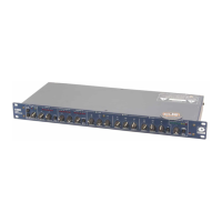
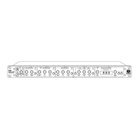
Input and Output Connections
Figure 9-1 illustrates how to connect the 528E to balanced and unbalanced sources and loads.
To operate the 528E from line level unbalanced sources, run a 2-conductor shielded cable (that’s
two conductors plus the shield) from the source to the 528E’s line input. At the source, connect
the low/minus side to the shield, these connect to the source’s ground; connect the high/plus side
to the source’s signal connection. At the 528E, the high/plus wire connects to pin 2, the low/minus
wire connects to pin 3, and the shield (always) connects to pin 1. This is the preferred method as
it makes best use of the 528E’s balanced input (even though the source is unbalanced). The other
alternative shown in Figure 3-1 converts the 528E’s balanced input into an unbalanced input at the
input connector. This works, but is more susceptible to hum and buzz than the preferred method.
There is no level difference between either method.
The 528E has two output connectors: XLR-male and TRS female. The XLR connector may be
confi gured for either microphone-level or line-level output. The TRS connector is always line level.
Refer to Appendix A for conversion instructions.
You can drive unbalanced loads with the 528E’s outputs by using the XLR connector with pin
3 left open. In an emergency (the show must go on), you can ground pin 3, but if you have the
choice...leave it open. If you must ground pin 3, it must be grounded at the 528E, rather than at the
other end of the cable. The price, regardless of whether or not pin 3 is grounded is 6dB less output
level. This can be easily made up via the output gain controls. If your system is wired with pin 3
hot, pin 2 must fl oat if you are driving an unbalanced load.
The 1/4-inch unbalanced output uses a TRS female jack with the ring contact wired to circuit
ground. This jack is unaffected by the internal output level switch. Unlike the XLR connector, using
this jack corrects the gain so that it is unity. The interstage patching jacks are half-normalled (only
the input jack breaks normal) TRS jacks wired for unbalanced operation. This means that the tip is
the signal connection, ring and sleeve are ground. This method of connection allows either TRS or
TS plugs to be used, with either balanced or unbalanced inputs or output on the remote equipment.
Aside from that, the TRS jack grabs the plug better. Ensure that your plug is fully inserted into the
jack.
The sidechain access jack for the dynamics processor uses a TRS jack wired as an insert jack. This
means that the ring connection is the send to and the tip connection is the return from the remote
processor. Figure 9-2 shows the wiring for the plug as well as the connections to/from the external
processor.
Phantom Powering Condenser Microphones
Most modern condenser microphones have provisions for being remotely powered via the mi cro -
phone cable. The dominant system in use today is the phantom power system which is compatible
with both condenser and non-condenser microphones (dynamics, ribbons, etc.). If your mi cro -
phone’s data sheet says that it is phantom powered, the 528E can power it
1
.
Another remote powering system exists called A-B powering, modulation lead powering, or T sys-
tem. A-B powering is incompatible with phantom powering as well as other non-powered micro-
phones.
The technical requirements for operation and/or compatibility are:
• The microphone must have a balanced, low-impedance output .
• The balanced output must be fl oating with respect to ground. If there is a center tap, it must
also fl oat with respect to ground. (In the past, it was common to ground the center tap of the
microphone’s output transformer. This was especially true of ribbon microphones.)
1
The DIN specifi cation (DIN 45 596) covering phantom powering specifi es the phantom powering voltage as an
open-circuit measurement. If you attempt to measure the phantom voltage, make sure that you do so with the
mi cro phone disconnected.
 Loading...