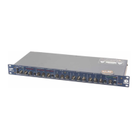
528E
23
For best results, the 528E should replace the mic preamp in your console or recording chain. If you
have to plug the 528E into a microphone input (-40 dBu nominal level), then you’ll need to pad (at-
tenuate) the output of the 528E down to microphone level. An internal jumper connection reduces
the 528E’s output to this level. Although a far preferable connection would be to bypass your
console’s mic preamp, this will work. When confi gured for mic-level output, the 528E’s circuitry
doesn’t care if phantom powering is or isn’t present at the console’s mic input. Ap pen dix A contains
instructions for altering the output level of the 528E.
Note: Padding (attenuating) the output of the 528E back to microphone level is a workable solution
towards interfacing the 528E into a console or system having only microphone level inputs. How-
ever workable, the ultimate per for mance of the 528E will be limited by the per for mance of your
system’s existing microphone preamps. If you can fi nd a way to bypass the existing microphone
preamps in your system, do so. It’ll be worth the trouble.
Using the 528E as a Channel Insert Device
The 528E can also be used as a channel-insert device with your console. Use the 528E’s line input
and line output as shown in Figure 7-3.
Using the 528E in an Effects Loop
Signal processors used in a console’s effects (send-receive) loop should not be insert or series
1
processors. A series processor means that you have to break the signal path to insert the pro ces sor.
Since using the effects loop does not break the signal path, we don’t recommend that you connect
the 528E here. Use the channel-insert jacks as described under the previous heading or insert the
528E between your console and your tape machine.
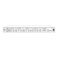
Using the Patch Points
Located on the rear panel are several TRS jacks. These jacks are the connections between the vari-
ous processors that make up the 528E. The jacks are half-normalled, which means that without any
plugs inserted, the signal fl ows through them via internal switching contacts. The term “half nor-
mal” means that only the input or return jack has switching contacts; inserting a plug into the output
or send jack does not break the signal path. This allows you to access the signal at various points in
the 528E’s signal path for use with external processors.
The patch point jacks can be used to insert additional processing into the signal path or perhaps
to rearrange the sequence in which the individual processors receive the input signal. Still another
possibility would be to use the parametric equalizer in the sidechain of the compressor/downward
expander (for additional information on using the sidechain, see the end of this chapter).
Inserting Additional Processing
Figure 7-4 shows an external processor inserted between the 528E’s equalizer and its output stage.
To insert additional (external) processing into the 528E’s signal path:
1. Decide where in the signal path you wish to insert the external processor.
2. Patch the appropriate output jack
on the 528E to the input jack of the
external processor. Use either a
TRS or TS patchcord.
3. Patch the output jack of the external
processor to the cor re spond ing
input jack on the 528E. Use either a
TRS or TS patchcord.
1
An insert or series processor is one that is inserted in series with the signal to be modifi ed. Gen er al ly speak ing,
series pro ces sors have a wet-dry mix control, however compressors, expanders, gates, equal iz ers, as well as the
528E, are all series processors that don’t.
STAGE
OU T P U T
PRE-AMPDE -E S S
OU T P U T I NP U TINPUT
SIDECHAIN
TIP=RETURN
RING=S END
OU T P U TINPUT
EXPANDER/COMPRES SOR
OU T P U T
UNBALANCED
OU T P U T
OU T P U T S T AGE
INPUT
EQUALIZER
E X T E R NAL AUDI O P R OCE S S OR
INPUTOUT P U T
LIN
Figure 7-4. Inserting ad di tion al processing
 Loading...