Installation
DC Power Connection
15247-201 Rev. B – April 2009 6502B RF Distribution User Guide
9
DC Power Connection
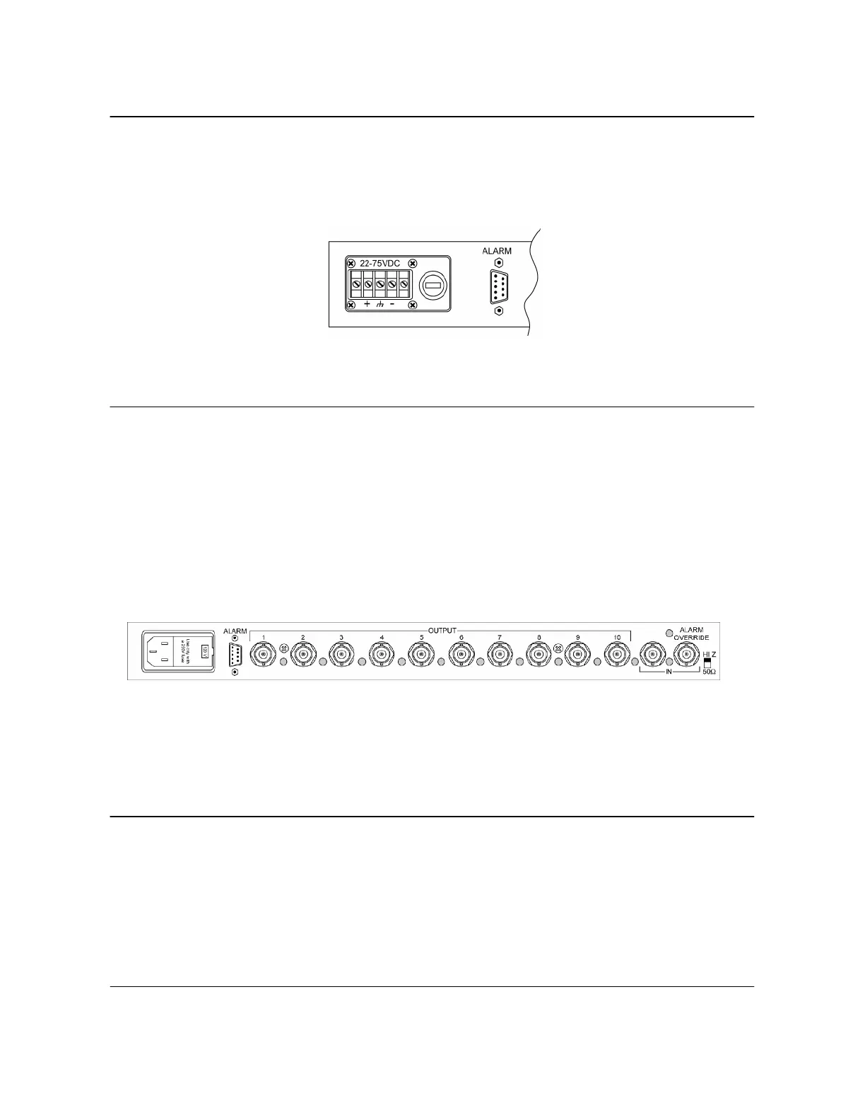
The Symmetricom 6502B (DC version) is powered from a DC source. The
connections are made at TB1 as shown in Figure 2. The voltage input may be 20
V to 75 V.
Figure 2 DC Power Connection
Signal Connectors
Connect the signal to be distributed to one of the two BNC connectors labeled
INPUT. Set the impedance switch to 50Ω (down) if only one 6502B module is to be
used. If multiple 6502B modules are used to obtain more than ten outputs, see
Figure 4.
Output cables may be connected in any order to the BNC connectors labeled 1 to
12. Refer to Figure 3.
Figure 3 Signal Connections
With the 6502B powered, the green power indicator on the front panel will
illuminate. The impedance switch should be set to 50Ω if there is only one module.
The red indicator next to the input signal is off to show that there is a good input
signal.
Daisy Chaining More Than One Module
If more than ten outputs are required, up to ten Symmetricom 6502B modules can
be driven by a common input signal to produce up to 100 outputs. Figure 4
illustrates this connection.
Artisan Technology Group - Quality Instrumentation ... Guaranteed | (888) 88-SOURCE | www.artisantg.com
 Loading...