15247-201 Rev. B – April 2009 6502B RF Distribution User Guide
11
Operation
Overview
The Symmetricom 6502B RF Distribution controls and indicators are described in
this chapter.
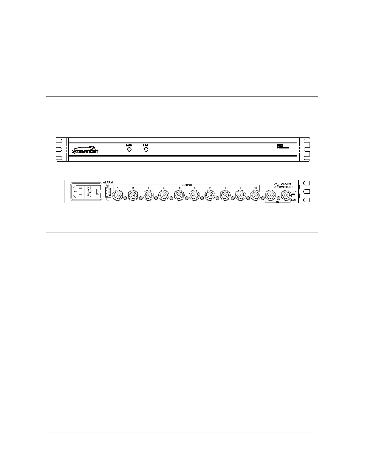
Figure 6: 6502B Distribution Front Panel
Figure 7: 6502B Distribution Rear Panel
Controls and Indicators
HI Z/50
Ω
This slide switch on the rear panel selects either the HI Z input impedance (un-
terminated) or the 50Ω input impedance. A 6502 installation of two or more (ten
maximum) units will set the switch to HI Z position on the module connected to the
source of the signal, and on all subsequent modules except the last module, which
is switched to the 50Ω position, providing proper termination for the signal.
ALARM OVERRIDE
When provided, the optional ALARM OVERRIDE toggle switch enables or disables
the ALARM relay output on the ALARM connector. This makes ALARM OVERRIDE
useful for suppressing audible alarms.
With ALARM OVERRIDE in the UP position, the ALARM relay is enabled and
changes states in the event of a signal failure. With ALARM OVERRIDE in the
DOWN position, the ALARM relay is disabled, forcing it into a normal (no alarm)
condition. ALARM OVERRIDE doesn’t affect the LED indicators.
POWER
LED on the front panel to indicate that power is applied. There is no power switch on
the 6502B. When power is connected, power is ON.
Artisan Technology Group - Quality Instrumentation ... Guaranteed | (888) 88-SOURCE | www.artisantg.com
 Loading...