1-7-2 T7400EA
3. Operate the unit for at least 20 minutes.
4. Press "2" button on the remote control unit and
select H-Adj Mode. (Press "2" button, then display
will change H-Adj and AGC.)
5. Press CH o / p buttons on the remote control unit
so that the display will change "0" to "7."
At this moment, choose display "0" to "7" when the
Frequency counter display is closest to
15.734kHz±300Hz.
6. Turn the power off and on again.
2-2. C-Trap Adjustment
Purpose: To get minimum leakage of the color signal
carrier.
Symptom of Misadjustment: If C-Trap Adjustment is
incorrect, stripes will appear on the screen.
Note: J271 (B-Out)--- Main CBA
1. Connect Oscilloscope to J271.
2. Input a color bar signal from RF input.
Enter the Service mode. (See page 1-4-1.)
3. Press "0" button on the remote control unit and
select C-TRAP Mode.
4. Press "CH o / p" buttons on the remote control
unit so that the carrier leakage B-Out (3.58MHz)
value becomes minimum on the oscilloscope.
5. Turn the power off and on again.
2-3. Y DL Time/Y SW LPF
Adjustment
Purpose: To get minimum leakage of the color signal
carrier.
Symptom of Misadjustment: If Y DL Time Adjust-
ment is incorrect, stripes will appear on the screen.
1. Enter the Service Mode. (See page 1-4-1.)
2. Y DL Time Adjustment: Press "0" button on the
service remote control unit twice to show "D-T" on
the display.
Y SW LPF Adjustment: Press "0" button on the
service remote control unit four times to show
"Y SW" on the display.
3. Y DL Time Adjustment: Select "2" by pressing
"CH o / p" buttons on the service remote control
to enter Y DL Time Adjustment mode.
Y SW LPF Adjustment: Select "1" by pressing
"CH o / p" buttons on the service remote control
to enter Y SW LPF Adjustment mode.
4. If needed, perform the following.
Test point Adj. Point Mode Input
J271
(B-OUT)
CH o / p
buttons
--- Color Bar
Tape M. EQ. Spec.
---
Oscilloscope
Pattern Generator
---
Figure
minimum
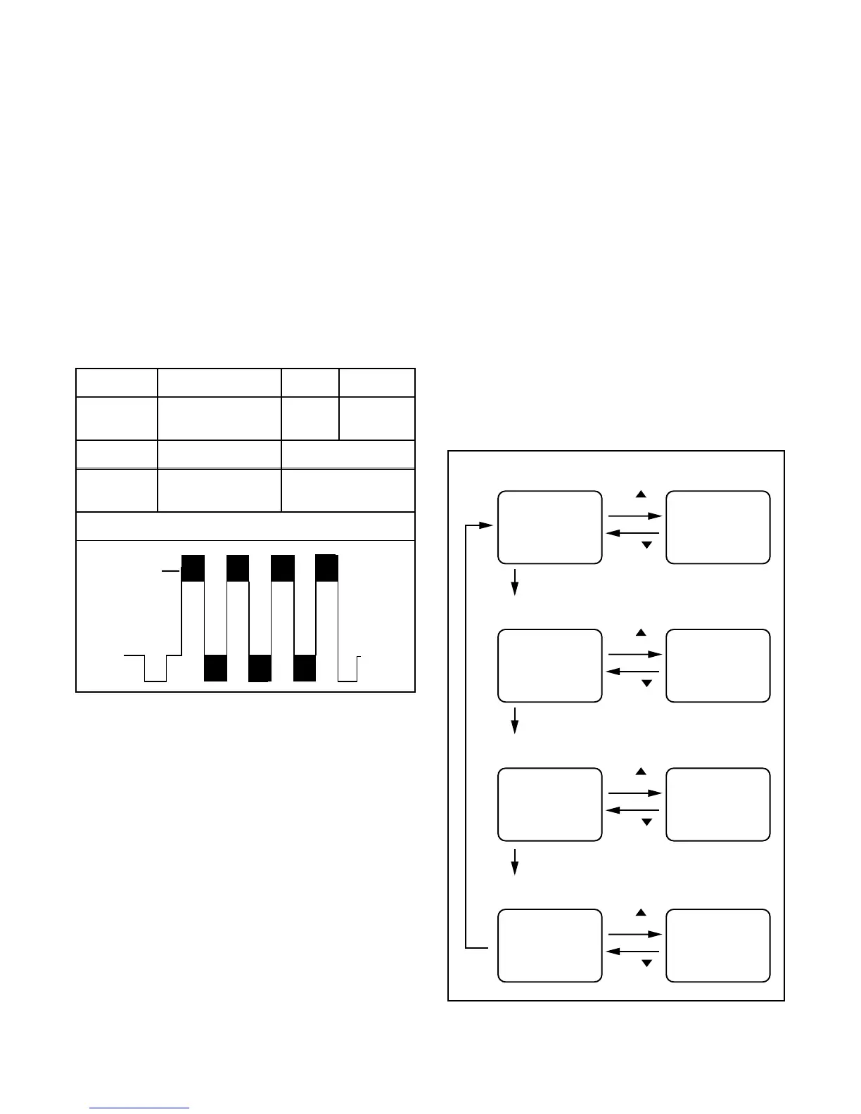
Fig. 2
Y DL Time Adj TV Adjustment
CH
button
D-T TV 0 D-T TV 1
button
CH
Y DL Time Adj EXT/PB Adjustment
CH
button
D-T EXT 0 D-T EXT 1
button
CH
"0" button
Y SW LPF Adjustment
CH
button
Y SW
button
CH
"0" button
0"
utton
C-TRAP Adjustment (Factory mode
CH
button
C-TRP 0 C-TRP 1
button
CH
"0" button
0 Y SW 1