EasyManuals Logo
Home>SYNAPTICON>Servo Drives>SOMANET Node 400

SYNAPTICON SOMANET Node 400 Documentation

Default Icon
27 pages
To Next Page IconTo Next Page
To Previous Page IconTo Previous Page
Page #13 background imageLoading...
Page #13 background image
2 Phase B
3 Phase C
4 Phase D
5 Ground
6 Main Power Supply 12-48 V *
7 Optional Logic Ground
8 Optional Logic Supply 12-24 V (20 W
max)**
* To be run with an appropriate extra-low voltage supply without contactors behind the power supply.
Further information can be found here
** not connected by default. Upon request only, please contact sales@synapticon.com
Grounding and attaching power and brake cables
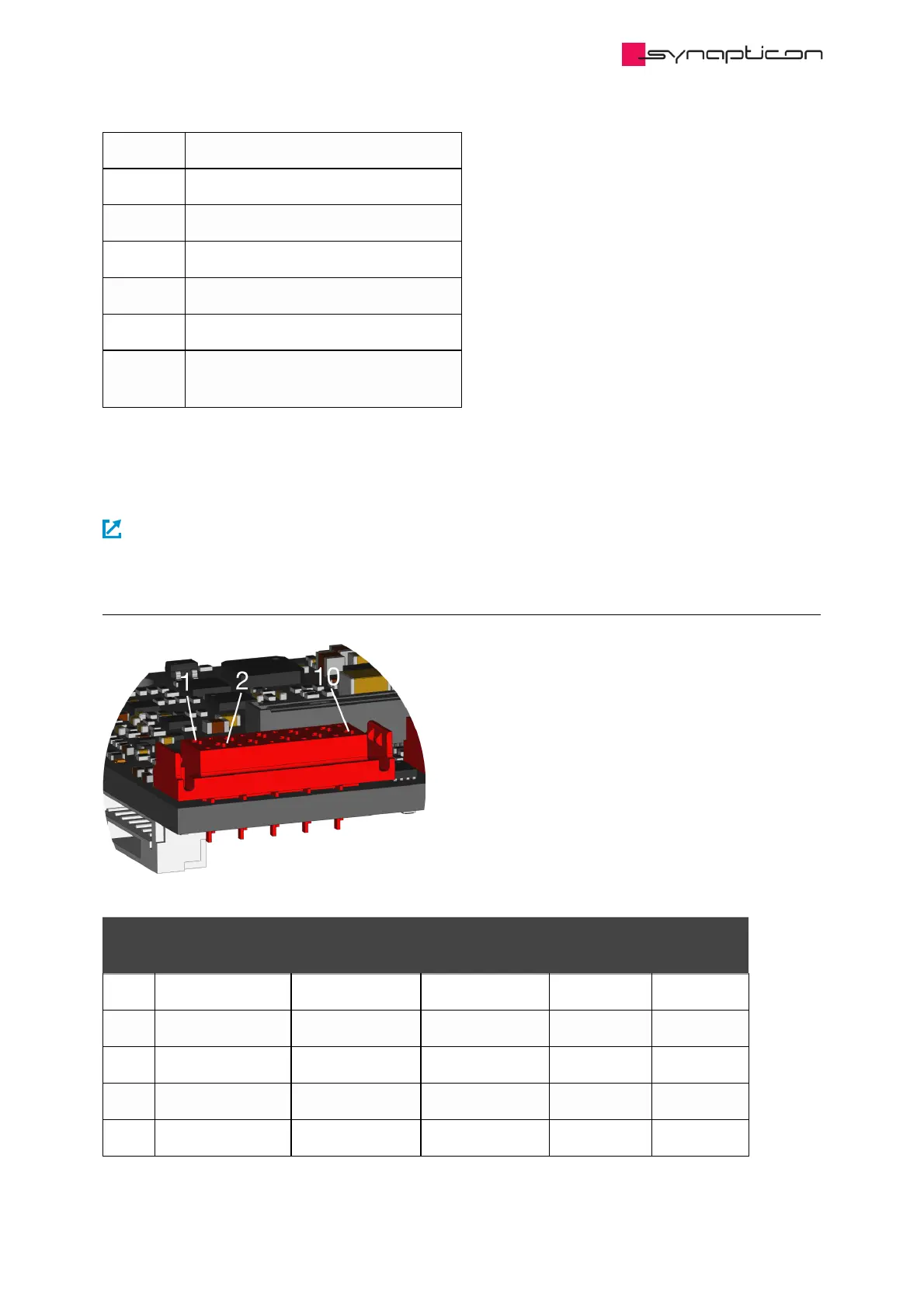
1.3.3.2 Encoder Port 1
Pin # ABI/ABZ (RS422) ABI/ABZ (TTL)* HALL (TTL)** BiSS
(RS422)
SSI (RS422)
1 MA- Clock-
2 5 V *** 5 V *** 5 V *** 5 V *** 5 V ***
3 Ground Ground Ground Ground Ground
4 MA+ Clock+
5 A- A W (C) SLO- Data-
Hardware Manuals / SOMANET Node / SOMANET Node rev.
D.3/D.4
© 2020 Synapticon GmbH | Daimlerstraße 26 | D-71101 Schönaich Documentation v 4.2.0 | Build: 2020-10-02 13/27

Other manuals for SYNAPTICON SOMANET Node 400

Questions and Answers:

Question and Answer IconNeed help?

Do you have a question about the SYNAPTICON SOMANET Node 400 and is the answer not in the manual?

SYNAPTICON SOMANET Node 400 Specifications

General IconGeneral
BrandSYNAPTICON
ModelSOMANET Node 400
CategoryServo Drives
LanguageEnglish

Related product manuals