10 QSG ti-Series Laser Ver 2.5
ti-Series Laser Quick Start Guide
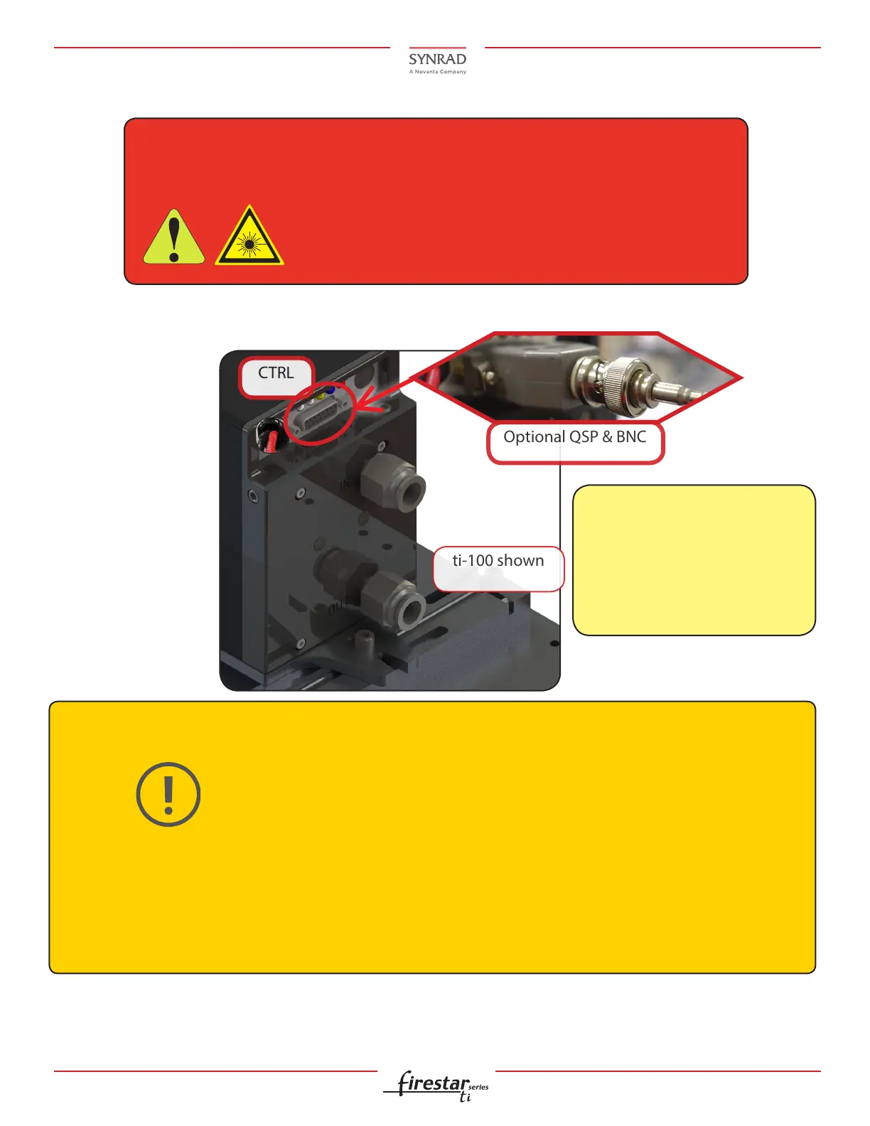
8. Connect the laser’s control BNC interface to the laser.
Control Connections:
Note:
The Quick Start Plug is
not included with SA
models, but may be
ordered separately. See
the Operation Manual
if using a Quick Start
Plug.
Caution
Possible equipment
damage
All control connections to ti-Series lasers are made through the 15-pin User I/O
connector on the laser’s rear panel. The User I/O port receives power commands
from SYNRAD UC-2000 Universal Laser Controller, or F3D/ marking head, and also
serves as the connection point for auxiliary signals between the laser and any
parts handling, automation, or monitoring equipment.
Potential
hazard
Danger
The Quick Start Plug bypasses the laser’s safety interlock
function, potentially exposing personnel to hazardous
invisible laser radiation.
If substituting power supplies, use a well-regulated VDC power supply with no more than 3 V overshoot
under a 10–90% modulation load. The use of short leads and terminations rated for the appropriate out-
put current is recommended.
Refer to the product specications for the required voltage range in the Operation Manual.
Do not reverse polarity when connecting the DC Power cable between the DC power supply and your
laser.

 Loading...