11 QSG ti-Series Laser Ver 2.5
ti-Series Laser Quick Start Guide
Electrical Connections:
9. Verify that input AC power to the DC power supply is physically locked out or disconnected.
10. Connect the Marking Head DC power VDC cable into the supply.
11.
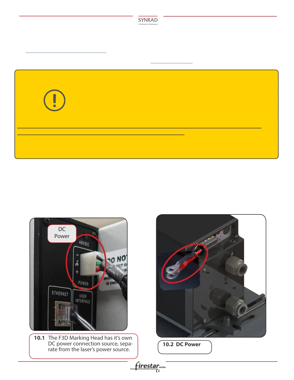
Connect the laser negative (black) and the positive (red) DC Power into the power supply.
10.1 The F3D Marking Head has it’s own
DC power connection source, sepa-
rate from the laser’s power source.
Caution
Possible equipment
damage
If using the Flyer 3D Marking Head: A DC power supply capable of providing 48 VDC
at 26-43 A depending on laser model, refer to the specications within the laser’s and
Flyer 3D operation manual.
For the Flyer 3D and the ti-Series laser, SYNRAD recommends the PS-48 DC power
supply which provides a maximum of 50A at 48 VDC. AC input requirements for the
PS-48 supply are 180-264 VAC, single phase (1Ø), 9.4 A max (@208 VAC), 47-63 Hz.
Please refer to the corresponding power supply manual located on our website.
Do not reverse polarity when connecting the DC Power cable between the DC power supply and the
ti-Series laser and Flyer 3D. Damage to the power supply may occur!
Because AC input connections and requirements vary from facility to facility, customers must provide the
AC power cable or wiring.
If you are using a SYNRAD Marking Head with your laser, and have completed control connections, refer to
the Marking Heads Quick Start Guide.
If you are using the SYNRAD controller, see the UC-2000 Quick Start Guide.

 Loading...