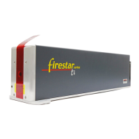
13 QSG ti-Series Laser Ver 2.5
ti-Series Laser Quick Start Guide
If using a UC-2000 Universal Laser Controller, refer to the UC-2000 Laser Controller Quick Start
Guide and it’s Operator’s Manual for setup and operation instructions located on our website.
IF not, continue below and to the next section.
Note:
Note: IF not using a SYNRAD controller for your laser, AND your OEM laser is put into service the rst
time, OR it has been re-located and has not been used yet in its new location, functionality should
be veried. Go to the following sections in this guide.
Note:
You circuit board provide a tickle signal and a pulse width modulated (PWM) Command signal to
the laser’s CTRL input connector. Refer to Controlling laser power in the Technical Reference chap-
ter in your laser’s Operation Manual for tickle and PWM Command signal/pinout descriptions.
When performing the initial start-up sequence, check that the factory-installed DB-9 jump-
er plug is installed. If not, you must provide the required Remote Interlock and Remote
Keyswitch signals to the DB-9 Connector. See the laser’s Operation Manual for DB-9 connec-
tions, pinouts and signal descriptions.
Important
Note:
The laser’s control board has a built-in tickle generator nor the applied PWM signals. If you are not using a
SYNRAD
®
UC-2000 Universal Laser Controller to operate the laser, see Controlling laser power’ in the laser’s
Operation Manual Technical Reference chapter for tickle signal descriptions.
Initial startup (Without a SYNRAD Controller):
Note: If you are using a SYNRAD Marking Head with your laser, and have completed control connections,
go to your Marking Head’s Quick Start Guide.
Initial startup:

 Loading...