V/D
S
ERIES
M
ECHANICAL ASSEMBLIES
Revision: 2.1 3-69
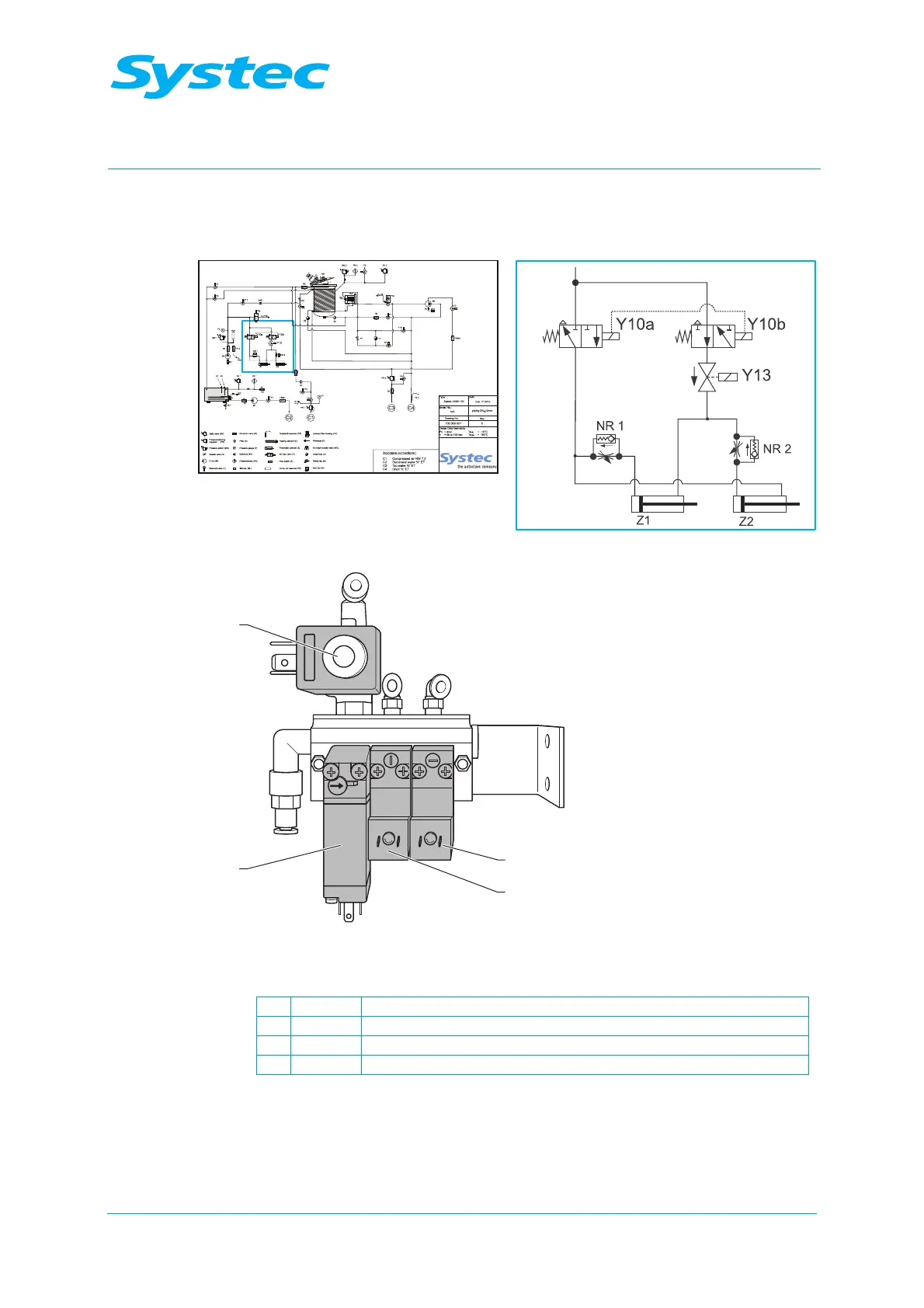
3.10.2 Pneumatic assembly
Position and function
Fig. 35: Pneumatic assembly: Position on pipe connection diagram
Fig. 36: Pneumatic assembly
1 Y11/Y8 Blow out cooling coil solenoid valve / vacuum pilot valve
2 Y10a Solenoid valve on door lock
3 Y10b Solenoid valve on door lock
4 Y13
Solenoid valve on door lock (230 V)
The Y10 (locking ring), Y11/Y8 (blow out cooling coil/vacuum pilot valve) and
Y13 (locking ring) connections are combined in the pneumatic assembly.
The connections Y10a (normally closed) and Y10b (normally open) are
controlled in parallel, but open and close in the opposing sense. This