D400-07-00 3 I56-279-04R
Dust covers can be used to help limit dust entry to the
detector, but they are not a substitute for removing the
detector during building construction. Remove any dust
covers before placing system in service.
Testing
Before testing the detector, look for the presence of the
flashing LED. If it does not flash, power has been lost to the
detector (check the wiring), or it is defective (return for
repair – refer to Warranty).
Detectors must be tested after installation and following
periodic maintenance. Notify the proper authorities that
the system is undergoing testing. The 1400 may be tested
as follows:
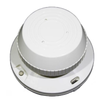
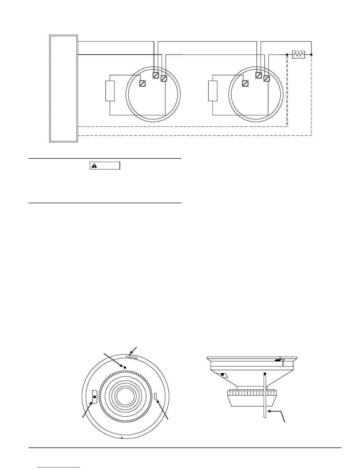
A. Recessed Test Switch
1. A test switch is located on the detector housing (See
Figure 4).
2. Push and hold the recessed test switch with a 0.1 inch
maximum diameter tool.
3. The LED on the detector should light within 5 seconds.
B. Test Module (System Sensor Model No. MOD400R)
The MOD400R is used with an analog or digital volt-
meter to check the detector sensitivity as described in
the test module manual.
C. Aerosol Generator (Gemini 501)
Set the generator to represent 4%/Ft. to 5%/Ft. obscu-
ration as described in the Gemini 501 manual. Using the
bowl shaped applicator, apply aerosol until the unit
alarms.
Notify the proper authorities that the system is back on-
line.
Detectors that fail these tests should be cleaned as
described under MAINTENANCE and retested. If the detec-
tors still fail these tests, they should be returned for repair.
+
REMOTE
ANNUNCIATOR
–
+
–
+
REMOTE
ANNUNCIATOR
CLASS A OPTIONAL WIRING
NOTE: IF REMOTE ANNUNCIATOR IS NOT USED, POLARITY TO DETECTOR MAY BE REVERSED.
EOL
RESISTOR
INITIATING
LOOP
UL LISTED
COMPATIBLE
CONTROL
PANEL
+
–
–
–
+
3
2
1
3
2
1
Figure 3. Wiring diagram for 1400 smoke detector used with two-wire control panel:
A78-1554-00
PUSH RECESSED TEST SWITCH WITH
A 0.1" MAX. DIAMETER TOOL.
TEST MODULE
SOCKET
LED
RECESSED
TEST SWITCH
TAMPER SLOT
Figure 4. Bottom and side views showing position of test switch:
A78-1554-03