2-WIRE I
3
DETECTOR WIRED IN STYLE D CONFIGURATION:
Any 2-wire i
3
smoke detector (2W-B, 2WT-B, 2WTA-B, or 2WTR-B) wired
in the Style D initiating device circuit (IDC) configuration requires the use
of a 2W-MOD2 module. This is because fire alarm control panels vary by
manufacturer on the implementation of Style D circuits. Therefore, the only
way to insure proper operation of 2-wire i
3
smoke detectors (2W-B, 2WT-B,
2WTA-B, or 2WTR-B) on Style D IDC’s is to use a 2W-MOD2 module. Refer to
the 2W-MOD2 installation manual, document D500-46-00, for Style D wiring
diagrams. The 2W-MOD2 installation manual may be downloaded from the
System Sensor web site at www.systemsensor.com.
INSTALLATION
Remove power from alarm control unit or initiating device circuits before in-
stalling detectors.
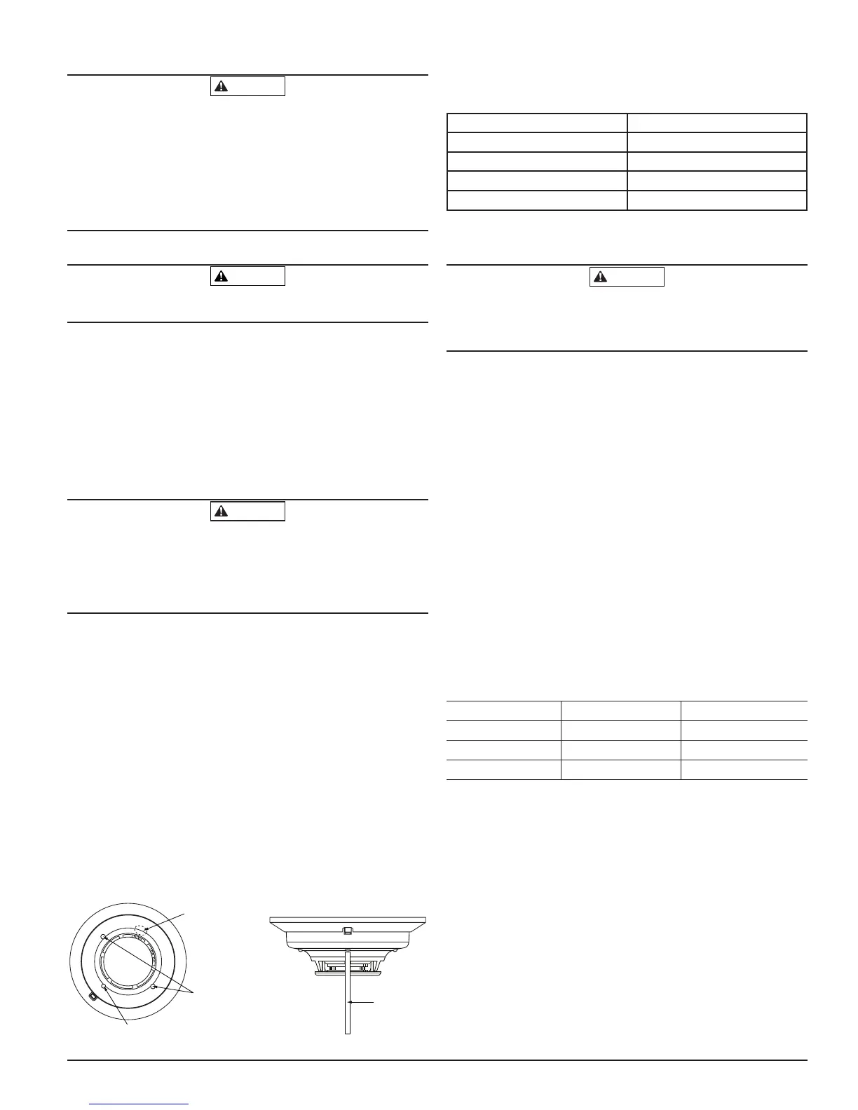
NOTE: To install units so that corresponding LEDs are lined up, refer to the
“Green LED” indicator on the base.
1. Wire the mounting base screw terminals per Figure 3a or Figure 3b, as
applicable.
2. Place detector on the base and rotate clockwise. The detector will drop
into the base and lock into place with a “click”.
3. After all detectors have been installed, apply power to the alarm control
unit.
4. Test each detector as described in Testing.
5. Reset all the detectors at the alarm control unit.
6. Notify the proper authorities that the system is in operation.
Dust covers are an effective way to limit the entry of dust into the smoke de-
tector sensing chamber. However, they may not completely prevent airborne
dust particles from entering the detector. Therefore, System Sensor recom-
mends the removal of detectors before beginning construction or other dust
producing activity. When returning the system to service, be sure to remove
the dust covers from any detectors that were left in place during construction.
TESTING
Detectors must be tested after installation and following maintenance.
NOTE: Before testing, notify the proper authorities that maintenance is being
performed and the system will be temporarily out of service. Disable the zone
or system undergoing maintenance to prevent any unwanted alarms.
Ensure proper wiring and power is applied.
After power up, allow 80 seconds
for the detector to stabilize before testing.
Test i
3
Series detectors as follows:
A. TEST SWITCH
1. An opening for the recessed test switch is located on the detector hous-
ing (See Figure 4).
2. Insert a small screwdriver or allen wrench (0.18˝ max.) into the test
switch opening; push and hold.
3. If the detector is within the listed sensitivity limits, the detector’s red
LED should light within five seconds.
FIGURE 4: RECESSED TEST SWITCH OPENING AND SENS-RDR POSITION
SWITCH WITH A
0.18≤ MAX.
DIAMETER TOOL
LED
RECESSED TEST SWITCH
POSITION SENS-RDR
AT AN ANGLE ON THE
OVAL AREA OR AT THE
CHAMBER OPENING
BY THE WORD “PAINT”
S0135-00
B. SMOKE ENTRY TEST
Canned aerosol simulated smoke (canned smoke agent) may be used for
smoke entry testing of the smoke detector. Tested and approved aerosol smoke
products are:
MANUFACTURER MODEL
Home Safeguard Industries 25S, 30S
SDi CHEK02 and CHEK06
SDi SOLOA4
SDi SMOKESABRE-01
When used properly, the canned smoke agent will cause the smoke detector
to go into alarm. Refer to the manufacturer’s published instructions for proper
use of the canned smoke agent.
Canned aerosol simulated smoke (canned smoke agent) formulas will vary by
manufacturer. Misuse or overuse of these products may have long term ad-
verse effects on the smoke detector. Consult the canned smoke agent manufac-
turer’s published instructions for any further warnings or caution statements.
C. DIRECT HEAT METHOD (MODELS 2WT-B AND 4WT-B ONLY)
Using a 1000-1500 watt hair dryer, direct the heat toward either of the thermis-
tors. Hold the heat source about 12 inches from the detector to avoid damage
to the plastic.
NOTE: For the above tests, the detector will reset only after the power source
has been momentarily interrupted.
If a detector fails any of the above test methods, its wiring should be checked
and it should be cleaned as outlined in the Maintenance section. If the detec-
tor still fails, it should be replaced.
Notify the proper authorities when the system is back in service.
LOOP VERIFICATION (MODELS 2W-B AND 2WT-B ONLY)
Loop verification is provided by the EZ Walk loop test feature. This feature
is for use with i
3
Series compatible control panels or the i
3
Series 2W-MOD2
module only. The EZ Walk loop test verifies the initiating loop wiring and
provides visual status indication at each detector.
1. Ensure proper wiring and power is applied. Wait approximately six min-
utes before performing EZ Walk test.
2. Place control panel or module in EZ Walk Test mode (refer to panel man-
ufacturer’s manual or 2W-MOD2 manual D500-46-00).
3. Observe the LEDs on each detector:
TABLE 3: EZ WALK TEST DETECTOR MODES
Green LED Red LED
Proper Operation Double blink 5 sec —
Out of Sensitivity — Double Blink 5 sec
Freeze Condition — Double Blink 10 sec
NOTE: The EZ Walk loop test must not be used instead of alarm testing.
3 I56-1800-014
02-02

 Loading...