D100-99-00 4 I56-2170-04R
©System Sensor 2003
System Sensor warrants its enclosed smoke detector to be free from defects in
materials and workmanship under normal use and service for a period of three
years from date of manufacture. System Sensor makes no other express war-
ranty for this smoke detector. No agent, representative, dealer, or employee of
the Company has the authority to increase or alter the obligations or limitations
of this Warranty. The Company’s obligation of this Warranty shall be limited to
the replacement of any part of the smoke detector which is found to be defective
in materials or workmanship under normal use and service during the three year
period commencing with the date of manufacture. After phoning System Sensor’s
toll free number 800-SENSOR2 (736-7672) for a Return Authorization number,
send defective units postage prepaid to: System Sensor, Returns Department, RA
#__________, 3825 Ohio Avenue, St. Charles, IL 60174. Please include a note
describing the malfunction and suspected cause of failure. The Company shall not
be obligated to repair or replace units which are found to be defective because of
damage, unreasonable use, modifications, or alterations occurring after the date
of manufacture. In no case shall the Company be liable for any consequential or
incidental damages for breach of this or any other Warranty, expressed or implied
whatsoever, even if the loss or damage is caused by the Company’s negligence or
fault. Some states do not allow the exclusion or limitation of incidental or con-
sequential damages, so the above limitation or exclusion may not apply to you.
This Warranty gives you specific legal rights, and you may also have other rights
which vary from state to state.
Three-Year Limited Warranty
Please refer to insert for the Limitations of Fire Alarm Systems
Electrical Specifications 2-wire 4-wire
System Voltage –Nominal: 12/24 12/24 V (Non-polarized for
2WTR-B and 4WTR-B)
Min.: 8.5 10 V
Max.: 35 35 V
Max. Ripple Voltage: 30 30 % peak to peak
of applied voltage
Avg. Standby Current: 50 50 µA average
Peak Standby Current: 100 — µA
Max. Alarm Current
4WTA-B, 4WTR-B: — 35 mA
4WTAR-B, 4WITAR-B: — 50 mA
2WTR-B: 130 — mA panel must limit
current
2WTA-B: 130*
Alarm Contact Ratings: — 0.5 A @ 30 V AC/DC
Form C Contact Ratings: 2 2 A @ 30 V AC/DC
Audible Signal
(temp-3 tone): 85 85 dBA min. in alarm or
supply polarity
reversed (Sounder
units only)
Remote Annunciator Output: 7 — mA maximum
EOL Relay: — 12/24 A77-716B
Reset Time (min): 0.3 0.3 seconds
Max. Start-up Capacitance: 0.1 — µF
Max. Initial Start-up Time: 45 15 seconds
Alarm Verification**
Start-up Time: 15 15 seconds
* Direct Power (Non-reverse Polarity): 130 mA limited by panel.
Reverse Polarity Power: 30 mA for the 2WTA-B in alarm; 12 mA for all other 2WTA-B
units on the loop. Add 25 mA for the RRS-MOD reversing relay alarm current.
** Assumes the panel’s alarm verification reset time is 10 seconds or less. Should the
alarm verification reset exceed 10 seconds, use the maximum initial start-up time.
Physical Specifications
Heat Sensor: 135°F (57.2°C)
Freeze Trouble: 41°F (5°C)
Operating Temperature Range: 32 to 100°F (0 to 37.8°C)
Operating Humidity Range: 0 to 95% RH non-condensing
Storage Temperature Range: –4 to 158°F (–20 to 70°C)
Diameter (including base): 5.3 inches
Height (including base): 2.0 inches
Weight: 7.1 oz.
FCC Statement
This device complies with part 15 of the FCC Rules. Operation is subject to the following two conditions: (1) This device may not cause harmful interference, and (2) this
device must accept any interference received, including interference that may cause undesired operation.
Note: This equipment has been tested and found to comply with the limits for a Class B digital device, pursuant to Part 15 of the FCC Rules. These limits are designed to
provide reasonable protection against harmful interference in a residential installation. This equipment generates, uses and can radiate radio frequency energy and, if
not installed and used in accordance with the instructions, may cause harmful interference to radio communications. However, there is no guarantee that interference
will not occur in a particular installation. If this equipment does cause harmful interference to radio or television reception, which can be determined by turning the
equipment off and on, the user is encouraged to try to correct the interference by one or more of the following measures:
– Reorient or relocate the receiving antenna.
– Increase the separation between the equipment and receiver.
– Connect the equipment into an outlet on a circuit different from that to which the receiver is connected.
– Consult the dealer or an experienced radio/TV technician for help.
Table 3: EZ Walk Test Detector Modes
|Green LED |Red LED
Proper Operation
|
Double blink 5 sec
|
—
Out of Sensitivity
|
—
|
Double Blink 5 sec
Freeze Condition
|
—
|
Double Blink 10 sec
NOTE: The EZ Walk loop test must not be used instead of alarm
testing.
Maintenance
NOTE: Before performing maintenance on the detector, notify
the proper authorities that maintenance is being performed and
the system will be temporarily out of service. Disable the zone or
system undergoing maintenance to prevent any unwanted alarms.
Power must be removed from the detector before performing
maintenance of any kind.
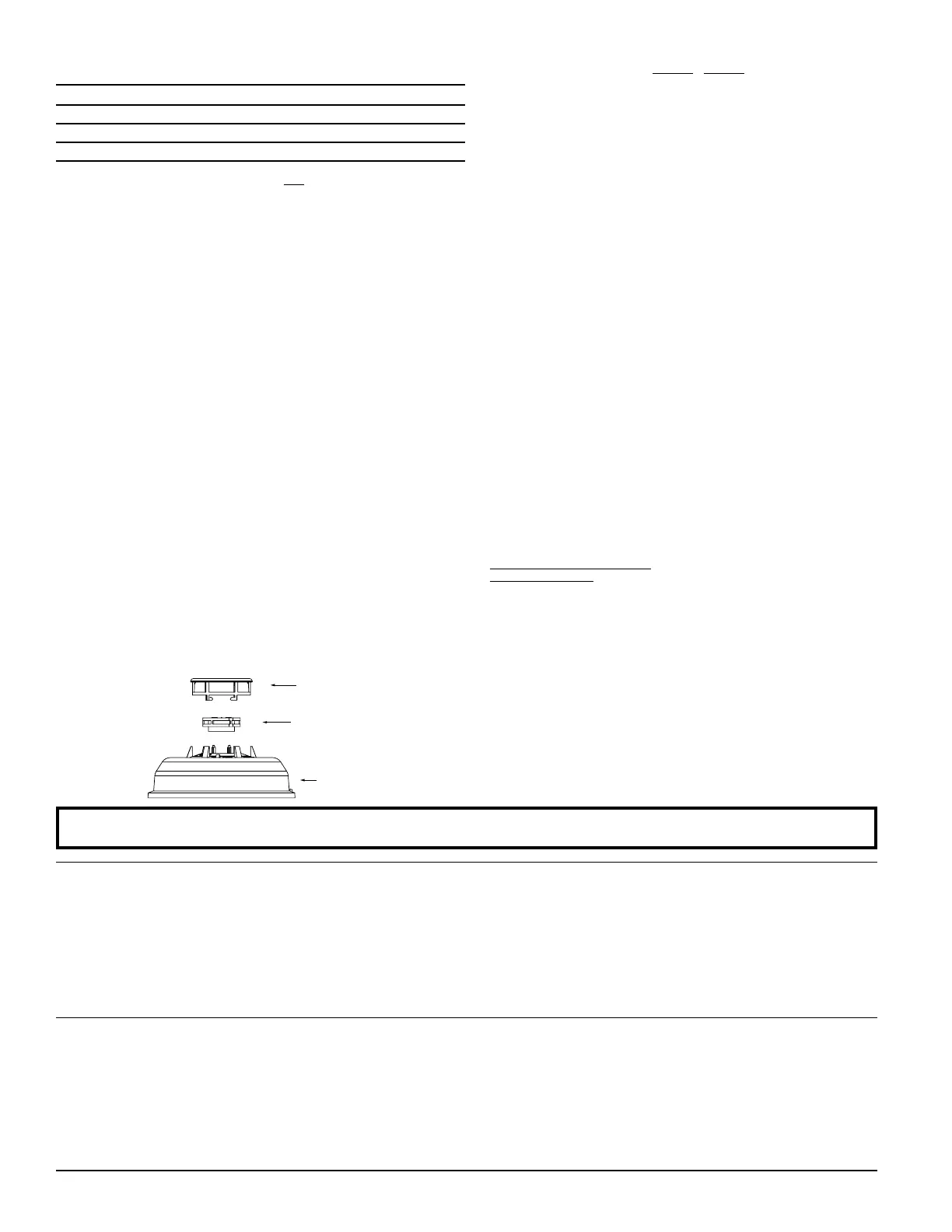
1. Remove the detector cover by turning counterclockwise. (See
Figure 5.)
2. Vacuum the cover or use canned air to remove any dust or
debris.
3. Remove the top half of the screen/sensing chamber by lifting
straight up (Figure 5).
4. Vacuum or use canned air to remove any dust or particles that
are present on both chamber halves.
5. Replace the top half of the screen/sensing chamber by aligning
the arrow on the screen/sensing chamber with the arrow on the
housing. Press down firmly until the screen/sensing chamber is
fully seated.
6. Replace the detector cover by placing it over the screen/sensing
chamber and turning it clockwise until it snaps into place.
7. Reinstall the detector and test. (See the Testing section.)
8. Notify the proper authorities when the system is back in service.
Figure 5: Removing Screen/Sensing Chamber
S0111-00
REMOVABLE
DETECTOR
COVER
SCREEN/SENSING
CHAMBER
(TOP HALF)
DETECTOR
HOUSING

 Loading...