kitchens, in garages, near furnaces, hot water heaters, or gas space heaters.
• In very cold or very hot areas.
• In wet or excessively humid areas, or next to bathrooms with showers.
• In dusty, dirty, or insect-infested areas.
• Near fresh air inlets or returns or excessively drafty areas.
Air con-
ditioners, heaters, fans, and fresh air intakes and returns can drive
smoke away from the detector.
Note: This unit is UL listed as containing a supplemental sounder and should
not be used as a primary sounder for evacuation.
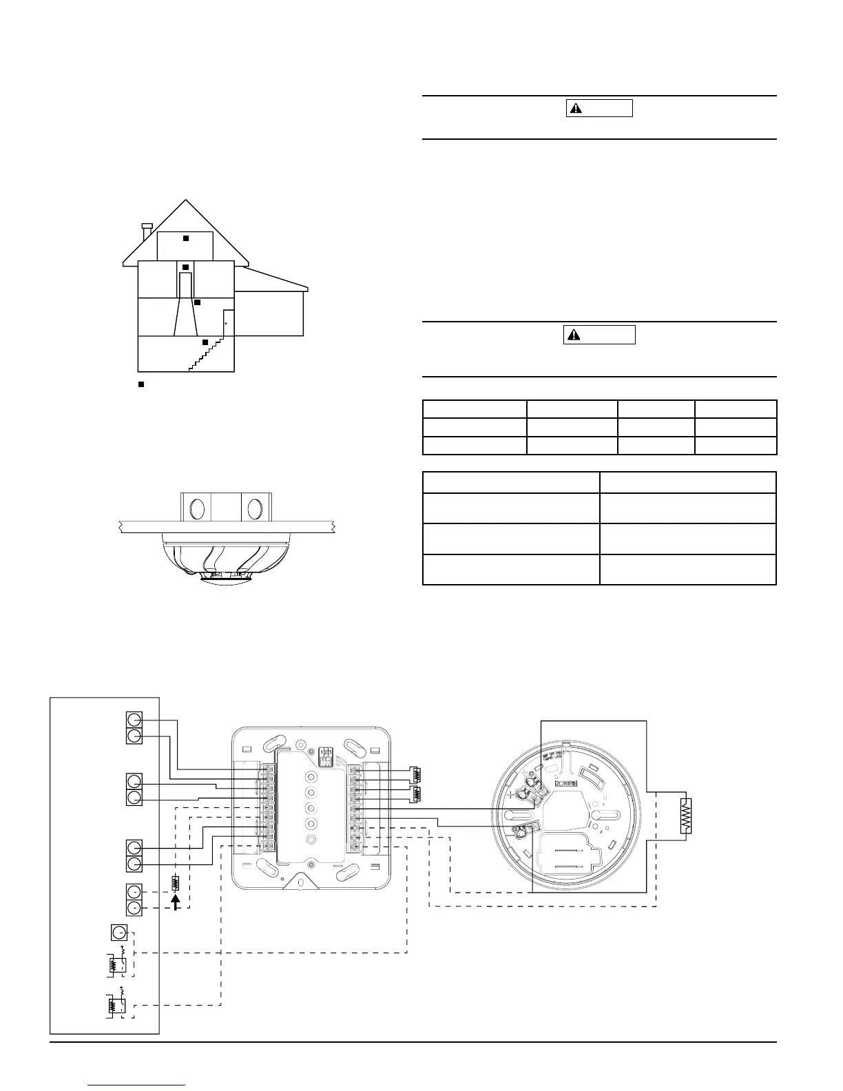
FIGURE 1: ALARM LOCATION DIAGRAM FOR RESIDENTIAL APPLICATION
LIVING
ROOM
BEDROOM BEDROOM
BEDROOM
KITCHEN
TO
BR
CLOSED
DOOR
BASEMENT
GARAGE
CARBON MONOXIDE/SMOKE ALARM
LOCATION FOR MULTI-LEVEL RESIDENCE
–
MOUNTING
The i
4
detector can be ceiling mounted or wall mounted:
1. To a single gang box, 2 in. by 4 in. box, 3½ in. or 4 in. octagonal or 3½
in. or 4 in. round ceiling
2. Direct mount to ceiling or to wall using drywall fasteners
FIGURE 2: MOUNTING OF DETECTOR
WIRING INSTALLATION GUIDELINES
All wiring must be installed in compliance with the NFPA 70 standards, Na-
tional Electrical Code, applicable state and local codes.
The screw terminals in the mounting base will accept 14-22 gauge wire.
Wire
connections are made by stripping approximately
3
/8" to ½" of insulation from
SS-500-003 2 I56-3747-001R
S0295-01
S0326-00
the end of the feed wire, inserting it into the proper base terminal, and tight-
ening the screw to secure the wire in place.
Do not put wires more than 2
gauge apart under the same clamping plate.
Remove power from alarm control unit or initiating device circuits before installing detectors.
1. Remove detector from packaging and separate the base from the detector head.
2. Wire the detector base screw terminals.
3. Screw the base of the detector onto an electrical box, or to the surface of
the wall or ceiling using the hardware included in the packaging.
4. Attach the detector head to the base by applying light pressure and rotat-
ing clockwise. The detector will lock in place when properly aligned.
5. After all detectors have been installed, apply power to the alarm control
unit. Refer to Table 3 for time to LED stabilization. Once stabilized, the
green LED will blink once every 5 seconds.
6. Test each detector as described in the Testing section.
7. Notify the proper authority that the system is in operation.
CAUTION
NFPA 72 recommends the installation of detectors only after completing construction or
any other dust producing activity
TABLE 2: LED INDICATION DURING POWER UP SEQUENCE
Green LED Red LED Blue LED
No Power OFF OFF OFF
Power on Reset Blink 5 Sec. Blink 5 Sec. Blink 5 Sec.
TABLE 3: POWER UP TIME TO FIRST ALARM / LED STABILIZATION
Power Up Time 45 Seconds
Power up time after
10 second reset
15 Seconds
LED Indication time
Typical: 45 seconds
Maximum: 55 seconds
Status LED indication
stabilization time
Typical: 55 seconds
Maximum: 268 seconds
TESTING
The detector must be tested after installation.
The detector has two discrete
test switches, one for smoke testing and one for CO testing.
The detector may
also be functionally tested using canned smoke and canned CO.
NOTE: Before testing, notify the proper authorities to avoid any nuisance alarms.
Ensure the proper wiring and power is applied to the detector.
After power
up, allow approximately 5 minutes for the detector to stabilize before testing.
COSMO-2W
3.9k
RESISTOR
(supplied
with module)
LOOP STYLE D WIRING
SMOKE
AUXPOWER
(resettable)
SMOKE
ZONE
CO
ZONE
MAINT.
ZONE
SMOKE
TRIGGER OUT
Panel
EOL
Resistors
COSMOD2W
ALL CIRCUITS ARE SUPERVISED
(EXCEPT TRIGGERS) AND MUST
BE POWER LIMITED
Panel
EOL
Resistor
CO
TRIGGER
OUT
BELL
OR
S0329-00
FIGURE 3:
COSMO-2W WIRING DIAGRAM

 Loading...


