SS-500-003 3 I56-3747-001R
3. If the detector is within the listed sensitivity limits, the sounder will
alarm temporal 3 and the red alarm LED will light up.
SMOKE SENSITIVITY READING
To measure the detector’s smoke sensitivity, the Infrared Sensitivity Reader
model #SENS-RDR should be used.
1. Point the SENS-RDR directly to the center of the detector at a distance of 1 to
10 feet. A broomstick can be attached to the SENS-RDR for extended reach.
2. The sensitivity will be displayed on the SENS-RDR. The SENS-RDR will
also display “replace” if a detector is found faulty.
SMOKE ENTRY TEST
1. With the detector in standby mode, spray UL listed compatible, canned
smoke into the detector.
2. When the detector senses the presence of the smoke, the sounder will
alarm temporal 3 and the red alarm LED will illuminate.
Note: On some panels, resetting a smoke alarm may require additional steps
at the keypad to clear the trouble conditions on CO and smoke mainte-
nance zones due to power loss to the module.
LOOP VERIFICATION (MODEL #COSMO-2W ONLY)
Loop verification is provided by the EZ Walk loop test feature. This feature is
for use with compatible control panels and System Sensor 2-wire detectors (i
4
Series model COSMO-2W and i
3
Series model 2WTA-B) installed with the COS-
MOD2W interface module only. The EZ Walk loop test verifies the initiating
loop wiring and provides visual status indication at each detector:
1. Ensure proper wiring and power is applied.
Wait approximately 6 min-
utes after power-up before performing the EZ Walk test.
2. Place COSMOD2W interface module into EZ Walk test mode by depress-
ing the recessed test button on the COSMOD2W Interface Module.
3. Observe the LED’s at each detector.
NOTE: The EZ Walk loop test should not be used in lieu of functional testing
(alarm, trouble and other functional tests) of the system.
CO TEST SWITCH
1. A recessed CO test switch is located on the detector housing and iden-
tified by text that says “TEST” next to it and “CARBON MONOXIDE”
above it.
(See Figure 5)
2. With the detector in standby mode, use a small screwdriver to press and re-
lease the CO test switch. Pressing the switch one time will enter into RealTest®
Mode (see instructions below), pressing two times will enter test mode.
3. If the test is successful, the blue LED will light up.
The detector and mod-
ule will automatically reset within 60 seconds.
If the detector fails either of the above test methods the CO cell or the detector
should be replaced.
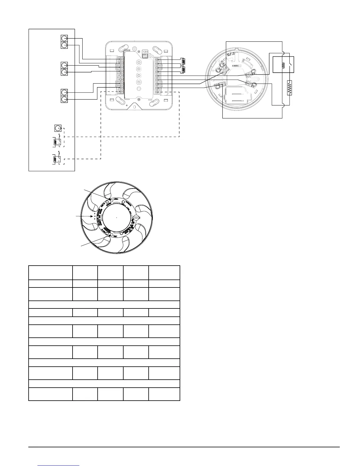
COSMO-4W
3.9k
RESISTOR
(supplied
with module)
SMOKE
POWER
(resettable)
SMOKE
ZONE
CO
ZONE
Panel
EOL
Resistors
COSMOD4W
EOL
RELAY
#EOLR-1
ALL CIRCUITS ARE SUPERVISED
(EXCEPT TRIGGERS) AND MUST
BE POWER LIMITED
CO
TRIGGER
OUT
SMOKE
TRIGGER OUT
BELL
OR
S0330-00
FIGURE 4:
COSMO-4W WIRING DIAGRAM
FIGURE 5: TEST BUTTON LOCATION AND OPERATION
GAS ENTRY
PORTS
TEST BUTTON
CARBON MONOXIDE
TEST BUTTON
SMOKE
TABLE 4: LED INDICATION & SOUNDER DURING TEST AND MAINTENANCE
GREEN
LED
RED LED
BLUE
LED
SOUNDER
Smoke Maintenance OFF Blink 5 Sec. OFF OFF
CO Trouble/
End-of-Life
OFF OFF Blink 5 Sec.
Intermittent chirp
after 30 days
Simultaneous Smoke Maintenance & CO Trouble/EOL
OFF Blink 5 Sec. Blink 5 Sec. OFF
EZ Walk Test® – Normal
Double
Blink 5 Sec.
OFF OFF OFF
EZ Walk® – Smoke Maintenance
OFF
Double
Blink 5 Sec.
OFF OFF
EZ Walk® – CO Trouble/End-of-Life
OFF OFF
Double
Blink 5 sec.
OFF
EZ Walk® – Smoke Maintenance & CO Trouble/End-of-Life
OFF
Double
Blink 5 sec.
Double
Blink 5 sec.
OFF
*NOTE: EZ Walk applies to COSMO-2W 2-wire model only.
SMOKE TEST SWITCH
1. A recessed smoke test switch is located on the detector housing and
identified by text that says "TEST" next to it and “SMOKE” above it. It is
the switch closest to the red LED. (See Figure 5)
2. With the detector in standby mode, use a small screwdriver to press and
release the smoke test switch.
S0327-00
 Loading...


