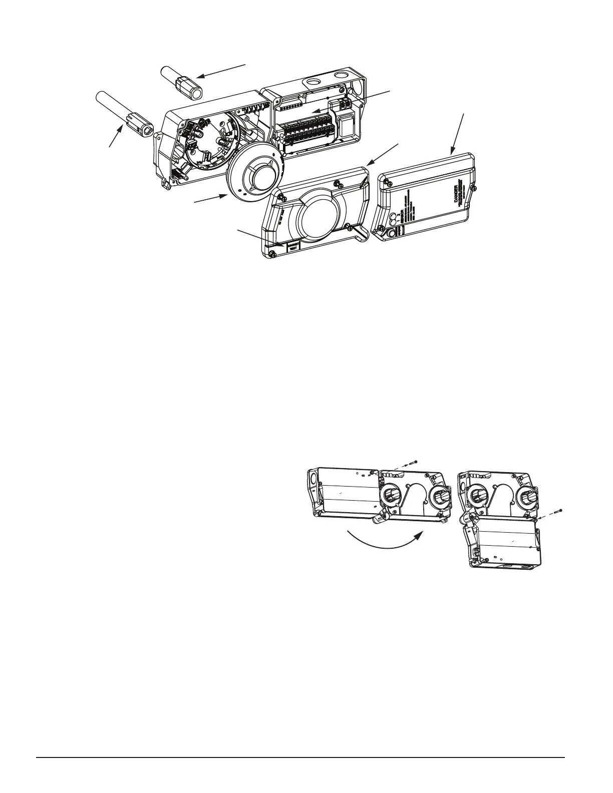
SENSOR MODULE
COVER
POWER BOARD MODULE COVER
SENSOR HEAD
METAL
SAMPLING TUBE
POWER BOARD
4-WIRE
MAGNET TEST LOCATION
(sold seperately)
[3] GENERAL DESCRIPTION
Smoke introduced into an air duct system will be distributed throughout the
entire building. Smoke detectors designed for use in air duct systems are
used to sense the presence of smoke in the duct.
Model D4120A and D4SA Duct Smoke Detectors utilize 4-wire photoelectric
technology for the detection of smoke. This detection method, when com-
bined with an efficient housing, samples air passing through the duct allow-
ing detection of a developing hazardous condition. When sufficient smoke is
sensed, an alarm signal is initiated and appropriate action can be taken to
shut off fans, blowers, change over air handling systems, etc. These actions
can facilitate the management of toxic smoke and fire gases throughout the
areas served by the duct system.
The D4120A and D4P120A detectors are designed to operate on 24 VDC/
VAC or 120 VAC. Alarm and supervisory relay contacts are available for
control panel interface, HVAC control, and other auxiliary functions. Auxiliary
relays are provided for fan shut down. Detector interconnection provides sig-
naling of up to 50 other detectors in the loop for multiple fan shut down. These
detectors are not designed for 2-wire applications. If units are powered by AC
power and monitored by a ULC listed FACP, the fire alarm zone needs to be
programmed as a monitor zone.
[3.1] DETECTOR FEATURE SET
-Utilizes 2D51A plug-in head
-2 sensors to 1 power board capability
-Cover missing signal
-Sampling tubes install from front or rear of detector
-Compatible with existing accessories
[4] CONTENTS OF THE DUCT SMOKE DETECTOR KIT
1. Sensor/power board assembly and cover(s)
2. Three #10 sheet metal screws for mounting
3. Drilling template
4. One sampling tube end cap
5. One plastic exhaust tube
NOTE: A sampling tube must be ordered to complete the installation. It must
be the correct length for the width of the duct where it will be installed. See
Table 1 on page 3 to determine the inlet tube required for different duct widths.
[5] DETECTOR INSTALLATION
[5.1] VERIFY AIR FLOW DIRECTION AND VELOCITY
Model D4120A detectors are designed to be used in air handling systems
with air velocities of 100 to 4000 feet per minute. Duct widths from 6 inches
to 12 feet can be accommodated. Be sure to check engineering specifica-
tions to ensure that the air velocity in the duct falls within these parameters.
If necessary, use a velocity meter (anemometer) to check the air velocity in
the duct.
[5.2] DETERMINE MOUNTING LOCATION AND CONFIGURATION
On ducts wider than 18 inches it is recommended that the detector be
mounted downstream of a bend, obstruction in the duct, or the supply or re-
turn air inlet.
Exception: Installation of duct detectors can be on or within a commercial
packaged rooftop heating and air-conditioning system, fire/smoke dampers
and economizers. They may be mounted in either the supply and/or return air
section as determined by local code.
Once a suitable location is selected, determine if the detector is to be
mounted in a side-by-side “rectangular” configuration or a top-over-bottom
“square” configuration as shown in Figure 2. If mounting in the square con-
figuration, remove the rear attachment screw, rotate the unit at the hinge, and
replace the screw into the new attachment hole as shown in Figure 2. Do
NOT remove the hinge screw during this process. Final installation approval
shall be based upon passing section 7.2.2 and/or 8.2.4 tests.
FIGURE 2.
DETECTOR AS SHOWN BELOW.
TO SECURE DETECTOR
IN PLACE.
H0550-00
[5.3] DRILL THE MOUNTING HOLES
Remove the paper backing from the mounting template supplied. Affix the
template to the duct at the desired mounting location. Make sure the template
lies flat and smooth on the duct.
[5.3.1] FOR RECTANGULAR SIDE-BY-SIDE MOUNTING
CONFIGURATION
Center punch at (4) target centers: (2) “A” for sampling tubes and (2) “B” for
the rectangular configuration mounting tabs as shown on mounting template.
Drill pilot holes at target “A” centers and cut two 1.375 inch diameter holes
using a 1
3
/8 inch hole saw or punch. Drill .156 inch diameter holes using a
5
/32
inch drill at target “B” centers.
[5.3.2] FOR SQUARE TOP-OVER-BOTTOM MOUNTING
CONFIGURATION OR D4SA SENSOR COMPONENT MOUNTING
Center punch at (4) target centers: (2) “A” for sampling tubes and (2) “C” for
the square configuration mounting tabs as shown on mounting template. Drill
2 I56-3102-003
7/8/2019
[2] FIGURE 1. EXPLODED VIEW OF DUCT SMOKE DETECTOR COMPONENTS
H0549-06

 Loading...


