pilot holes at target “A” centers and cut two 1.375 inch diameter holes using
a 1
3
/8 inch hole saw or punch. Drill .156 inch diameter holes using a
5
/32 inch
drill at target “C” centers. If desired, drill an additional .156 inch hole at the
location of one of the mounting tabs on the lower housing.
[5.4] SECURE THE DUCT DETECTOR TO THE DUCT
Use two (rectangular configuration) or three (square configuration) of the pro-
vided sheet metal screws to screw the duct detector to the duct.
CAUTION: Do not overtighten the screws.
[6] SAMPLING TUBE INSTALLATION
[6.1] SAMPLING TUBE SELECTION
The sampling tube must be purchased separately. Order the correct length,
as specified in Table 1, for width of the duct where it will be installed. It is rec-
ommended that the sampling tube length extend at least
2
/3 across the duct
width for optimal performance.
TABLE 1. SAMPLING TUBES RECOMMENDED FOR DIFFERENT
DUCT WIDTHS
Outside Duct Width Sampling Tube Recommended*
Up to 1 ft. DST1
1 to 2 ft. DST1.5
2 to 4 ft. DST3
4 to 8 ft. DST5
8 to 12 ft. DST10 (2-piece)
*Must extend a minimum of
2
/3 the duct width. These sampling tubes can only
be used with new InnovairFlex duct smoke detectors.
The sampling tube is always installed with the air inlet holes facing into the
air flow. To assist proper installation, the tube’s connector is marked with an
arrow. Make sure the sampling tube is mounted so that the arrow points into
the airflow as shown in Figure 3. Mounting the detector housing in a vertical
orientation is acceptable provided that the air flows directly into the sampling
tube holes as indicated in Figure 3. The sampling tube and exhaust tube
can be mounted in either housing connection as long as the exhaust tube is
mounted downstream from the sampling tube.
FIGURE 3. AIR DUCT DETECTOR SAMPLING TUBE
ARROW MUST FACE
INTO AIR FLOW
AIR FLOW
DIRECTION
H0551-00
CAUTION: The sampling tube end cap, included with the detector, is critical
to proper operation of the duct smoke detector. The end cap is needed to
create the proper air flow to the sensor of the duct smoke detector. Once any
sampling tube length adjustments are made, plug the end of the sampling
tube with the provided end cap.
A plastic exhaust tube is included with the unit to be installed if needed. Install
into the housing connection that is downstream from the sampling tube con-
nection. The exhaust tube can be installed from the front or back of the detec-
tor. A longer 1 foot exhaust tube, model ETX, is available as an accessory in
cases where the molded exhaust tube does not extend at least 2 inches into
the duct.
[6.2] SAMPLING TUBE INSTALLATION
1. For tubes shorter than the width of the duct, slide the sampling tube,
with installed end cap, into the housing connection that meets the airflow
first. Position the tube so the arrow points into the airflow as shown in
Figure 3. Per NFPA sampling tubes over 3 feet long should be sup-
ported at the end opposite the duct detector. In ducts wider than 8 feet,
work must be performed inside the duct to couple the other section of
the sampling tube to the section already installed using the
1
/2 inch con-
duit fitting. Make sure that the holes on both sections of the air inlet
sampling tube are lined up and facing into the airflow.
2. For tubes longer than the width of the duct, the tube should extend out of
the opposite side of the duct. Drill a
3
/4 inch hole in the duct opposite the
hole already cut for the sampling tube. Ensure that the sampling tube
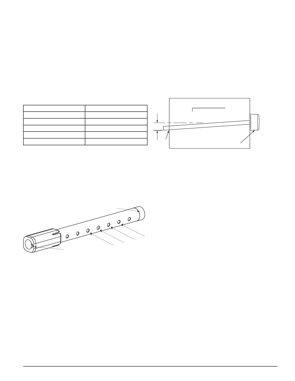
is angled downward from the duct smoke detector to allow for moisture
drainage away from the detector. The sampling tube should be angled
at least 1/4” downward for every 12” of duct width per Figure 4. There
should be 10 to 12 holes spaced as evenly as possible across the width
of the duct. If there are more than 2 holes in the section of the tube ex-
tending out of the duct, select a shorter tube using Table 1. Otherwise,
trim the tube to leave approximately 1 to 2 inches extending outside
the duct. Plug the end with the end cap and tape closed any holes in
the protruding section of tube. Be sure to seal the duct where the tube
protrudes.
FIGURE 4.
DETECTOR
3
/
4
˝
HOLE
12˝
1
/
4
˝
2˝
H0215-00
NOTE: Air currents inside the duct may cause excessive vibration, espe-
cially when the longer sampling tubes are used. In these cases, a 3 inch floor
flange (available at most plumbing supply stores) may be used to fasten the
sampling tube to the other side of the duct. When using the flange/connector
mounting technique, drill a 1 to 1
1
/4 inch hole where the flange will be used.
[6.3] MODIFICATIONS OF SAMPLING TUBES
There may be applications where duct widths are not what is specified for the
installation. In such cases, it is permissible to modify a sampling tube that is
longer than necessary to span the duct width.
Use a 0.193 inch diameter (#10) drill and add the appropriate number of
holes so that the total number of holes exposed to the air flow in the duct is
10 to 12. Space the additional holes as evenly as possible over the length of
the tube.
NOTE: This procedure should only be used as a temporary fix and is not
intended as a substitute for ordering the correct length tubes.
[7] MEASUREMENT TESTS
[7.1] AIR FLOW
The D4120A is designed to operate over an extended air speed range of
100 to 4000 FPM. To verify sufficient sampling of ducted air, turn the air han-
dler on and use a manometer to measure the differential pressure between
the two sampling tubes. The differential pressure should measure at least
0.01 inches of water and no more than 1.11 inches of water. Because most
commercially available manometers cannot accurately measure very low
pressure differentials, applications with less than 500 FPM of air speed may
require one of the following: 1) the use of a current-sourcing pressure trans-
mitter (Dwyer Series 607) per Section 7.2, or 2) the use of aerosol smoke per
section 12.5.3.
[7.2] LOW FLOW AIR FLOW TEST USING DWYER SERIES 607
DIFFERENTIAL PRESSURE TRANSMITTER
Verify the air speed of the duct using an anemometer. Air speed must be at
least 100 FPM. Wire the Dwyer transmitter as shown in Figure 5. Connect
the leads of the meter to either side of the 1000Ω resistor. Allow unit to warm
up for 15 seconds. With both HIGH and LOW pressure ports open to ambient
air, measure and record the voltage drop across the 1000Ω resistor (mea-
surement 1), 4.00 volts is typical. Using flexible tubing and rubber stoppers,
connect the HIGH side of the transmitter to the sampling tube of the duct
smoke detector housing, and the LOW side of the transmitter to the exhaust
tube of the duct smoke detector housing. Measure and record the voltage
drop across the 1000Ω resistor (measurement 2). Subtract the voltage re-
corded in measurement 1 from the voltage recorded in measurement 2. If the
3 I56-3102-003
7/8/2019

 Loading...


