Do you have a question about the System Sensor WFD40 and is the answer not in the manual?
| Type | Waterflow Detector |
|---|---|
| Retard Time | Adjustable, 0-90 seconds |
| Communication | N/A (Mechanical Device) |
| Humidity Range | 10% to 93% non-condensing |
| Waterflow Sensitivity | 4 – 10 GPM |
| Enclosure | NEMA 4 rated |
| Operating Temperature | 32°F to 120°F (0°C to 49°C) |
| Contact Ratings | 10 A @ 125/250 VAC; 2.5 A @ 30 VDC |
Details technical characteristics and operational limits of the waterflow detector.
Contains crucial information for users to read and save for proper installation and operation.
Explains how the vane-type waterflow detector functions and activates.
Lists the different models of waterflow detectors covered by this manual.
Provides essential prerequisites and standards for the correct installation of the detector.
Details electrical connections and wiring requirements for the waterflow detector.
Explains how to adjust the pneumatic delay mechanism for proper operation.
Outlines the steps for testing the waterflow detector's functionality after installation.
Provides instructions for maintaining the detector and replacing faulty components.
Lists important limitations and considerations for the effective use of waterflow detectors.
Details the warranty terms and conditions for the waterflow detector product.
Details technical characteristics and operational limits of the WFDT/WFDTH detectors.
Contains crucial information for users to read and save for proper installation and operation.
Provides guidance on tee fitting dimensions required for detector installation.
Explains how the vane-type waterflow detector functions and activates.
Lists compatible pipe tee types for the WFDT/WFDTH detectors.
Provides essential prerequisites and standards for correct installation of the detectors.
Details the step-by-step process for mounting the WFDT/WFDTH waterflow detectors.
Outlines the steps for testing the waterflow detector's functionality before initial use.
Details electrical connections and wiring requirements for the WFDT/WFDTH detectors.
Explains how to adjust the pneumatic delay mechanism for proper operation.
Outlines the steps for testing the waterflow detector's functionality after installation.
Provides instructions for maintaining the detector and replacing faulty components.
Lists important limitations and considerations for the effective use of waterflow detectors.
Details the warranty terms and conditions for the waterflow detector product.
Details technical characteristics and operational limits of the WFDTNR detector.
Contains crucial information for users to read and save for proper installation and operation.
Provides guidance on tee fitting dimensions required for detector installation.
Explains how the vane-type waterflow detector functions and activates.
Lists compatible pipe tee types for the WFDTNR detector.
Provides essential prerequisites and standards for correct installation of the detector.
Details the step-by-step process for mounting the WFDTNR waterflow detector.
Outlines the steps for testing the waterflow detector's functionality before initial use.
Details electrical connections and wiring requirements for the WFDTNR detector.
Provides instructions for maintaining the detector and replacing faulty components.
Lists important limitations and considerations for the effective use of waterflow detectors.
Details technical characteristics and operational limits of the OSY2 gate valve switch.
Contains crucial information for users to read and save for proper installation and operation.
Provides general advice and considerations for installing the OSY2 supervisory switch.
Addresses installation challenges and solutions specific to narrow yoke valves.
Addresses installation challenges and solutions specific to limited clearance valves.
Details the step-by-step process for installing the OSY2 gate valve supervisory switch.
Outlines the procedure for testing the supervisory switch's operation.
Lists important limitations and considerations for the effective use of supervisory switches.
Details the warranty terms and conditions for the supervisory switch product.
Details technical characteristics and operational limits of the PIBV2 supervisory switch.
Contains crucial information for users to read and save for proper installation and operation.
Provides general information on the PIBV2 switch for post indicator and butterfly valves.
Details the step-by-step installation process for PIBV2 on post indicator valves.
Details the step-by-step installation process for PIBV2 on butterfly valves.
Provides general installation procedures and considerations for PIBV2 switches.
Explains how to reverse the switch action for different valve configurations.
Lists important limitations and considerations for the effective use of supervisory switches.
Details the warranty terms and conditions for the supervisory switch product.
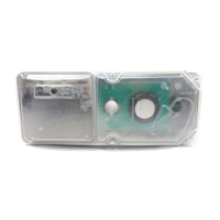
Details technical characteristics and operational limits of the cover tamper switch.
Provides general information about the function and application of the cover tamper switch.
Provides essential prerequisites and standards for installing the cover tamper switch.
Details the step-by-step process for mounting the cover tamper switch.
Details electrical connections and wiring requirements for the cover tamper switch.
Outlines the procedure for testing the cover tamper switch's functionality.
Details the warranty terms and conditions for the cover tamper switch product.
Details technical characteristics and operational limits of the 546-8000 cover tamper switch.
Provides general information about the function and application of the 546-8000 cover tamper switch.
Details the wiring procedure for the 546-8000 cover tamper switch.
Details the warranty terms and conditions for the 546-8000 cover tamper switch product.
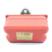
Details technical characteristics and operational limits of the EPS10 alarm pressure switches.
Contains crucial information for users to read and save for proper installation and operation.
Explains how the pressure switch operates based on pressure changes and settings.
Details the steps for installing the EPS10 alarm pressure switches.
Details how to adjust the factory settings for pressure alarm response on EPS10 switches.
Details the warranty terms and conditions for the pressure switch product.
Details technical characteristics and operational limits of EPS40/EPS120 supervisory pressure switches.
Contains crucial information for users to read and save for proper installation and operation.
Explains how the pressure switch operates based on pressure changes and settings.
Details the steps for installing the EPS40/EPS120 supervisory pressure switches.
Details how to adjust factory settings for pressure alarm response on EPS40/EPS120 switches.
Provides specific adjustment instructions for single-switch EPS40/EPS120 models.
Provides specific adjustment instructions for dual-switch EPS40/EPS120 models.
Details the warranty terms and conditions for the pressure switch product.
Details technical characteristics and sound output of SSM and SSV alarm bells.
Contains crucial information for users to read and save for proper installation and operation.
Provides general information about the alarm bells and relevant standards.
Outlines the procedure for testing the alarm bell's functionality.
Details the steps for installing the SSM and SSV alarm bell mechanisms.
Explains how the sound level measurements for alarm bells are made and specified.
Lists important limitations and considerations for the effective use of alarm bells.
Details the warranty terms and conditions for the alarm bell product.