5
Installation & Wiring
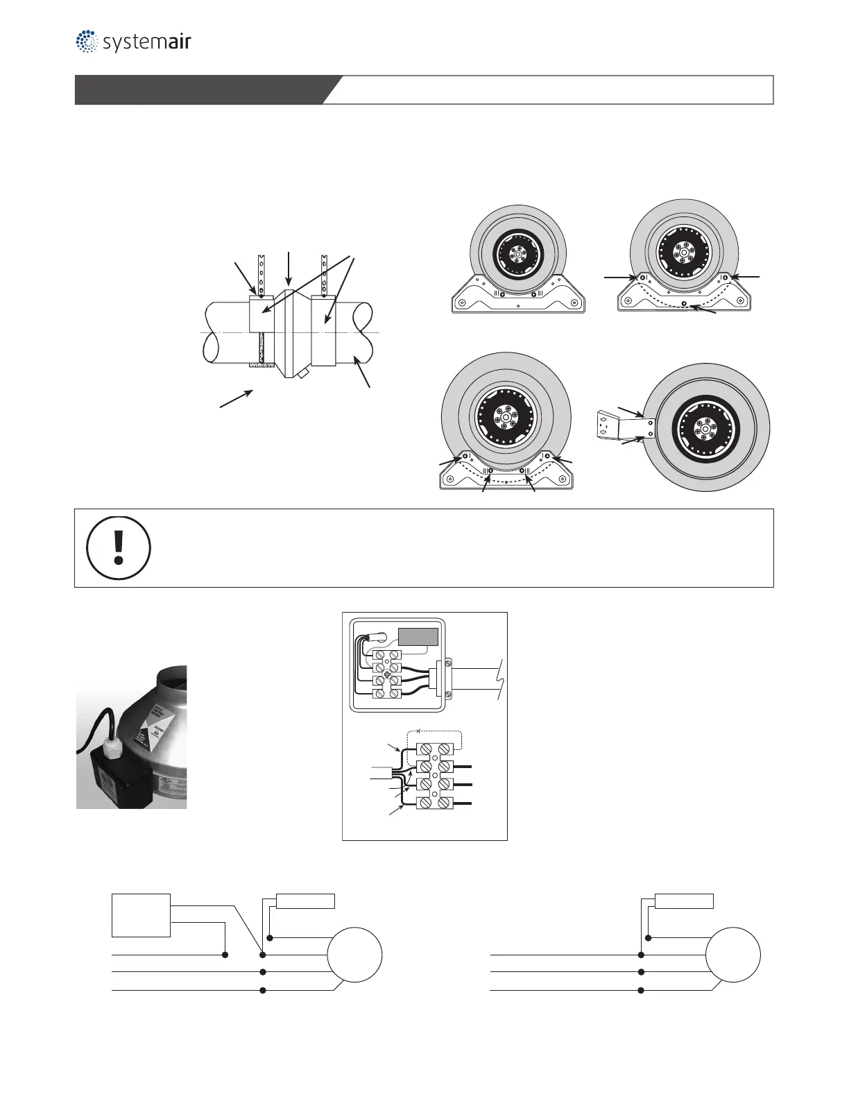
Illustration 2
Mounting Bracket & Screw Locations
Fans may be
suspended
without special
mounting
brackets.
Clamp Fastener
Duct Fan
Screws
Spiral duct
Vibration absorbing material
Models
• 4-EF
• 5-EF
Models
• 4XL-EF
• 5XL-EF
Models
• 6-EF
Models
• 6XL-EF
• 8-EF/8XL-EF
• 10-EF/10XL-EF
SPECIAL WIRING PRECAUTIONS
All installation should be wired according to the following diagrams.
Failure to comply will cause the motor to “hum” or not work.
Maximum torque that can be applied to the terminal block screws is 0.79 Nm (7 lb-in).
INSTRUCTION FOR 120V and 230V MOTORS
Motor
Speed
Control
Capacitor
Motor
Black (L)
White (N)
Green (GND)
Green
Brown
Black
Blue
With motor speed controller
Capacitor
Motor
Brown
Black
Blue
Without motor speed controller
Brown
Capacitor
Blue
Ground
Ground
Black
Green/Yellow
N
N
L
N
L
Capacitor
L
N
Ground
Supply voltage
Brown
Motor
Leads
L (Black)
N (White)
Ground
Black
Blue
Green/Yellow
Capacitor
3 wire motor 4 wire motor
Note
Model K-C comes pre-wired with
three prong power cord.
Note
Liquid tight wiring must be
used for outside applications.
Green
Black (L)
White (N)
Green (GND)
Note: Select control based on line voltage
Note:
Fans are furnished with either 120V
motors or 230V motors. The motors
are not dual voltage.
 Loading...