English
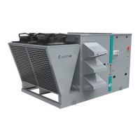
44 SysAer
Main
menu Q0
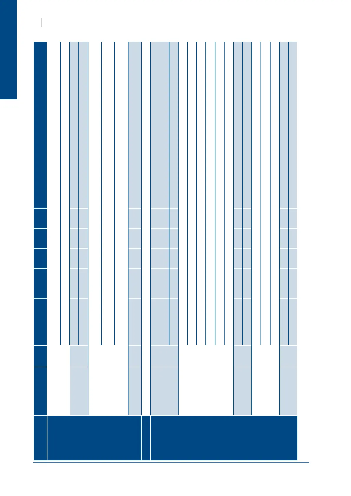
Item
Screen
code
Parameter Unit Min Fact. Max Description / Note
MAINTENANCE
Digital / Analogue
outputs test
Aw
Condenser fan 1 OFF/ON/% OFF/0 The condenser(s) fan(s) are basically driven by the compressors ON/OFF. But if they
Condenser fan 2 OFF/ON/% OFF/0 are driven by analog outputs, they can be tested with an analog value.
Analogue outputs Ax
Economizer opening % 0 0 100 (option)
Hot water valve % 0 0 100 Hot water coil proportionnal valve (option)
Gas outlets Ay
Gas burner capacity V 0 0 10.0
When manual output is above 3.5V, the correspondent digital output activates the
gas burner.
Gas stage 1 OFF/ON OFF/0
Gas stage 2 OFF/ON OFF/0
New password Az
New maintenance
pwd
- 0 - 9999
HISTORY
See Alarm log part
INPUTS /
OUTPUTS
Temperature
sensors
I1
Room °C
Gives the value of each sensor (if present), including the manual offset of the
Maintenace part.
Outdoor °C
Supply °C (option)
EEV circuit 1 and 2
dedicated sensors
(available only with
RTC units)
I2
EEV1 % Electronic Expansion Valve opening (circuit 1)
EP1 bar Evaporating Pressure (circuit 1)
CST1 °C Suction Temperature (circuit 1)
EEV2 % Electronic Expansion Valve opening (circuit 2)
EP2 bar Evaporating Pressure (circuit 2)
CST2 °C Suction Temperature (circuit 2)
Humidity sensors I3
Room %rH (option)
Outdoor %rH (option)
Superheat / Air quality I4
Superheat 1 K Circuit 1 superheat (calculated from EP1 and CST1), only on RTC unit
Superheat 2 K Circuit 2 superheat (calculated from EP2 and CST2), only on RTC unit
Air quality % (option)
Condensers /
defrost sensors
I5
Circuit 1 °C Condenser(s) or defrost sensor(s), depending on Summer or Winter mode and unit
Circuit 2 °C configuration