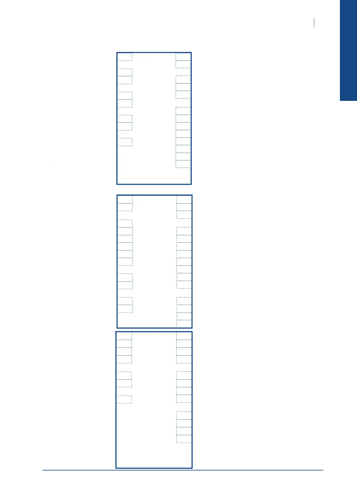
English
D2
D1
X8
X7
X6
X5
X4
X3
X2
X1
B3
B2
B1
DL1
DO2
DO1
Q6
Q5
Q4
Q3
Q1
POL423
Water inlet temperature
Water outlet temperature
Air temperature
Evaporation pressure
Condensation pressure
Backflow temperature
Phase sequence and cut-out controller
Thermal protection compressor
Thermal protection fan
External on/off contact
Configurable external input
Water flow contact
Water pressure
High speed fan
Slow speed fan
Electric heater
4-way valve
Compressor 2
Compressor 1
Alarm output
Modulating fan
Pump
Heat exchanger temperature
DU2
DU1
D2
D1
X8
X7
X6
X5
X4
X3
X2
X1
B3
B2
B1
DL2
DL1
DO2
DO1
Q8
Q7
Q6
Q5
Q4
Q3
Q2
Q1
POL687
Water inlet temperature
Water outlet temperature
Air temperature
Circuit 1 Evaporation pressure
Circuit 1 Condensation pressure
Circuit 1 Intake temperature
Circuit 1 Backflow temperature
Circuit 1 Heat exchanger temperature
Circuit 1 therm. protect. compressor 1
Circuit 1 therm. protect. compressor 2
Circuit 1 therm. protect. fan
External on/off contact
Configurable external input
Water flow contact / lack of water pressure switch
Thermal protection pump 1
Thermal protection pump 2
Circuit 1 HP transducer
Circuit 1 High speed fan
Circuit 1 Slow speed fan
Antifreeze electric heater
Pump 2
Pump 1
Circuit 1 4-way valve
Circuit 1 Compressor 2
Circuit 1 Compressor 1
Circuit 1 crankcase heater
Alarm output
X12
X11
X10
X9
X8
X7
X6
X5
X4
X3
X2
X1
DL1
DO2
DO1
Q4
Q3
Q2
Q1
POL96U
Circuit 2 Condensation pressure
Circuit 1 Evaporation pressure
Circuit 2 therm. protect. fan
Circuit 2 therm. protect. compressor 2
Circuit 2 therm. protect. compressor 1
Circuit 2 Heat exchanger temperature
Circuit 2 Backflow temperature
Circuit 2 Intake temperature
Modulating pump control
Circuit 2 Modulating fan
Circuit 1 Modulating fanCircuit 2 Compressor 1
Circuit 2 Compressor 2
Circuit 2 4-way valve
Circuit 2 Crankcase heater
Circuit 2 Slow speed fan
Circuit 2 High speed fan
Circuit 1 HP transducer
3SysAqua
1. DEFINITION
1.2. CONTROLLER INPUTS/OUTPUTS SYSAQUA 25/30/35/40/45/55/65/75/90/105/125
1.1. CONTROLLER INPUTS/OUTPUTS SYSAQUA 140/150/170/190/210

 Loading...


