English
0.0°C
0.0°C
--------
0.0°C
0.0°C
0.0 bar
--------
0.0 K
100.0%
0.0°C
0.0°C
0.0 bar
--------
45.2°C
42.3°C
0.0%
Stage 1
off
off
Coil T.
Outer air T.
------------------------------
Discharge T.
Condensing T.
Condensing P.
------------------------------
Surperheat
Exp. valve
Suction T.
Evaporating T.
Evaporating P.
------------------------------
Leaving water T.
Entering water T.
Source Fan
Source Fan
Compressor 2
Compressor 1
1/19Circuit 2
0.0°C
0.0°C
--------
0.0°C
0.0°C
0.0 bar
--------
0.0 K
100.0%
0.0°C
0.0°C
0.0 bar
--------
45.2°C
42.3°C
0.0%
Stage 1
off
off
Coil T.
Outer air T.
------------------------------
Discharge T.
Condensing T.
Condensing P.
------------------------------
Superheat
Exp. valve
Suction T.
Evaporating T.
Evaporating P.
------------------------------
Leaving water T.
Entering water T.
Source Fan
Source Fan
Compressor 2
Compressor 1
1/19Circuit 1
Heating
Cooling
Automatic
1/3
Low load
Reduced mode
On
Off
Automatic
1/5
off
0.0%
0.0%
44°C
44°C
8.0°C
8.0°C
Heating
Reduce mode
Circuit 2
Circuit 1
Supply pump
Present capacity
Load required
Current setp. heat
Heating setp.
Current setp. cool
Cooling setp.
S/W hmi
Op. mode HMI
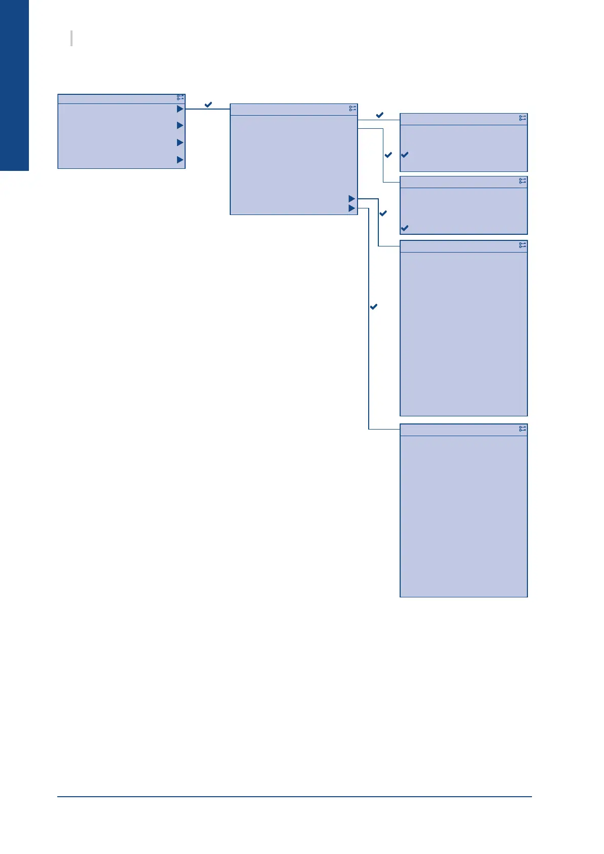
1/11Status
Access
Services
Commissioning
Status
6 SysAqua
This menu enables the nal user to check and modify the various
operating points of SysAqua
The nal user can manipulate the following settings:
² Active mode
² Heat/cool mode
² Cool mode temperature setting
² Heat mode temperature setting
It can also be used to view the following operating settings:
² Effective heat and cool temperature settings. A difference
between the set temperature and effective temperature
indicates that weather compensation is enabled.
² Requested load:
heat requirement calculated according to the setpoint value
and the values of the different sensors
² Current capacity:
heat capacity supplied by SysAqua
² Auxiliary pump:
status of the auxiliary pump
² Circuit 1
² Circuit 2
2.1.4. MENUS
2.1.4.1. STATUS MENU

 Loading...


