English
To perform electrical wiring of the unit, please refer to the wiring diagram pasted on the unit
casing.
Caution
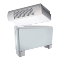
12 SysCoil Comfort
SEE APPENDIX
All fan coil units are designed for operation under 230 volts, single phase, 50 or 60 cycles .
A voltage variation of ± 10 % with regard to nominal voltage 230 V is acceptable.
9. ELECTRICAL CONNECTIONS
WARNING
Before carrying out any work on the equipment,
make sure that the electrical power supply is
disconnected and that there is no possibility
of the unit being started inadvertently.
Non-compliance with the above instructions
can lead to injury or death by electrocution.
SE 4546 SysCoil Comfort AC motor terminal block 230V 50Hz/60Hz +/- 10%
SE 4548 SysCoil Comfort AC motor TBMV-4P/2PEH 230V 50Hz/60Hz +/- 10%
SE 4729 SysCoil Comfort AC motor SysLogic 230V 50Hz/60Hz +/- 10%
SE 4550 SysCoil Comfort EC motor terminal block 230V 50Hz/60Hz +/- 10%
SE 4552 SysCoil Comfort EC motor TBMV-4P/2PEH 230V 50Hz/60Hz +/- 10%
SE 4730 SysCoil Comfort EC motor SysLogic 230V 50Hz/60Hz +/- 10%
SE 4554 SysCoil Comfort EC motor terminal block without Ecospeed3 230V 50Hz/60Hz +/- 10%
SE 4555 SysCoil Comfort AC motor TBMV C/O 230V 50Hz/60Hz +/- 10%
SE 4556 SysCoil Comfort AC motor TBMV 2P/2P REV 230V 50Hz/60Hz +/- 10%
SE 4557 SysCoil Comfort EC motor TBMV 2P/2P REV 230V 50Hz/60Hz +/- 10%
9.1. WIRING DIAGRAM AND LEGEND
9.2. POWER SUPPLY
The electrical installation must be performed by a fully qualied electrician, and in accordance with local
electrical standards and the wiring diagram corresponding to the unit model.
Any modication performed without our prior authorisation may result in the unit’s warranty being declared
null and void.
The power supply cable section must be sufcient to provide the appropriate voltage to the unit’s power
supply terminals, both at start-up and under full load operating conditions.
The power supply cable shall be selected in accordance with the following criteria:
1. Power supply cable length.
2. Maximum unit starting current draw – the cables shall supply the appropriate voltage to the unit
terminals for starting.
3. Power supply cables’ installation mode.
4. Cables’ capacity to transport the total system current draw.
Short circuit protection shall be provided. This protection shall comprise fuses or circuit breakers with high
breaking capacity, mounted on the distribution board.
A device to disconnect all the power conductors with an approved minimum opening distance must be
included in the mains power supply according to best installation practices.
9.3. ELECTRICAL CONNECTIONS
 Loading...