26
7 - Product Description
7.1 General Information
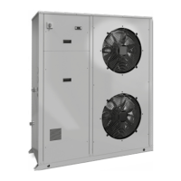
Syscroll Air EVO HP units are one-block type with one refrigerant
circuit. They are intended to cool down the water required for any
air-conditioning application as well as any other fluid, such as for
example glycol water.
These units are completely assembled at works. They are equipped
with all the refrigerating connections and the internal electrical wiring
required for a rapid installation on the field.
An operation test is performed after assembly, with water flowing
through the refrigerant/water exchanger in order to make sure that
every refrigerating circuit is properly working. The refrigerating
circuits of every unit are pressure tested before inspection, drained
and charged with R410A.
A low noise level is the result of a careful study. It is achieved on
chillers by using technologically advanced components without
negatively affecting the operation performances and limits of the
units.
Syscroll Air EVO HP models can cool down chilled water at a
temperature between + 18 and - 8 °C.
Syscroll Air EVO HP heat pump models can warm up water at a
temperature between 20 °C and 55 °C.
All units can operate with a double set point.
Body and Frame
The base and frame of these units are made with galvanized steel
elements, assembled with stainless steel screws. All panels can
be removed to ensure easy access to internal components. All
galvanized steel parts are protected by epoxy powder paint.
Compressors
Units are equipped with a scroll compressors, with brushless direct
current motor (BLDC) type.
The compressors are assembled on rubber shock absorbers. They
are cooled down by the refrigerant gas.
Compressors are powered on and off by the microprocessor of the
unit control system which is intended to control the delivery of the
thermal refrigerating capacity.
Evaporators
Evaporators are made of stainless steel plates. They are thermally
insulated by means of a thick flexible insulating mattress with closed
cells. The maximum operating pressures correspond to 10 bar
for the water side and to 45 bar for the refrigerant side. Antifreeze
protection for the water in the exchangers is ensured by electrical
heaters and differential pressure switches. The water side of these
exchangers is connected by manifolds which will provide for the
connection to the plant by means of one single 1”1 gas threaded
attachment.
Condensing coils
Condensers are coils made of copper tubes arranged in staggered
rows and mechanically expanded inside an aluminium finned pack
with blue fins treatment as a standard.
The maximum operating pressure on the refrigerant side of the
condensing batteries is 45 bar.
Condenser Fans
The condenser fans are of a helical type. They are directly coupled
and have an impeller with wing contoured aluminium blades.
Each fan is equipped with a galvanised steel accident-prevention
protection which is painted after manufacture. The fans motors
are completely closed. They have an IP54 protection degree and a
protection thermostat embedded in the windings.
Fans Control
All models are equipped with a single-phase voltage fan speed
controller using the principle of phase control to adjust the effective
voltage output to the load, based on the phase of the PWM control
signal according the pressure measured on the heat exchanger.
Refrigerating Circuits
Each unit has a single refrigerating circuit equipped with an external
service valves intended to measure the refrigerant pressure and
charge, a sight glass with a humidity indicator, a dryer filter and a
electronic expansion valve.
Refrigerating circuits are also complete with a high and low pressure
switch as well as a high and low transducer.
Control Supply Panel
All components of the control system and those necessary to start
the motors are shop connected and tested. The control compartment
contains an electronic card and a control board with an external
keyboard and display, to show the operational functions, as well as
the intervention of the alarms and the working blocks.

 Loading...