40
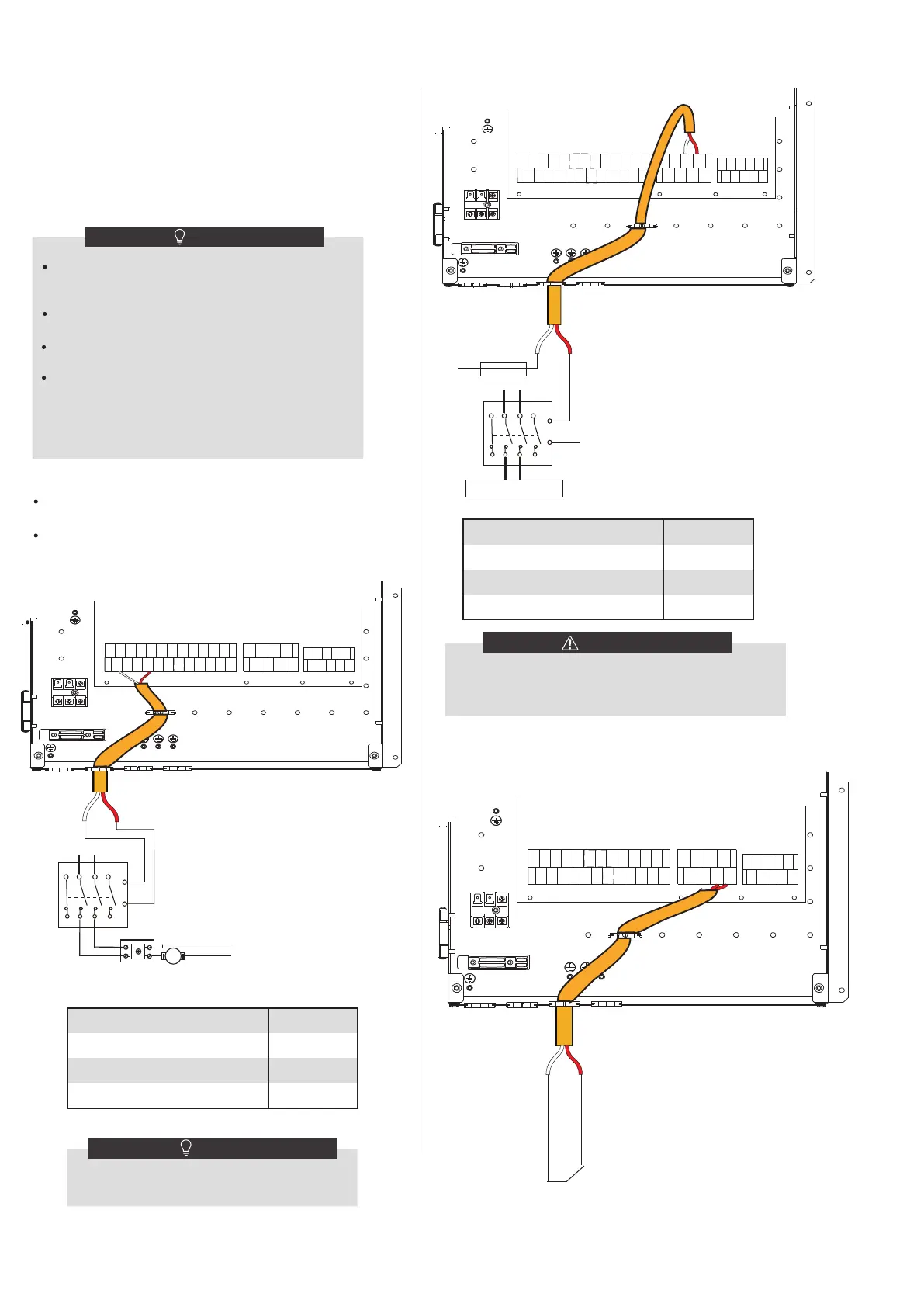
Control port signal type
Voltage
Maximum running current(A)
Wiring size(mm
2
)
Type 2
220-240VAC
0.2
0.75
The unit only sends an ON/OFF signal to the
heater.
NOTE
Control port signal type
Voltage
Maximum running current(A)
Wiring size(mm
2
)
Type 2
220-240VAC
0.2
0.75
This part only applies to Basic. For Customized, cause there
is an interval backup heater in the unit, the indoor unit
should not be connected to any additional heat source.
WARNING
8) For additional heat source control:
KM6
FUSE
Power supply
7 5 3 1
A1
A2
2468
L
N
Additional heat source
�
�
2019
18
����
CN11
1
2
3
4
5
6
7
8
9
10
CN7 CN30
27 28
1 2 3 4 5 6 7
8
9 10 11 12
13 14 15
16
17 21
22
23
24
7) For tank booster heater:
KM4
Power supply
7 5 3 1
A1
A2
2468
ATCO
TCO
�
�
����
CN11
25
26
1
2
3
4
5
6
7
8
9
10
CN7 CN30
27 28
29 30
31
32
13
16
NOTE
a) Procedure
Connect
the cable to the appropriate terminals as shown
in
the picture.
Fix
the cable with cable ties to the cable tie mountings
to
ensure stress relief.
C.2 When unit detect voltage is 12VDC between CL and COM,
zone2
turn on according to climate temp curve. When
unit
detect voltage is 0V between CL and COM, zone2 turn off.
C.3
When HT-COM and CL-COM are detected as 0VDC,
unit
turn off.
C.4 when HT-COM and CL-COM are detected as 12VDC,
both
zone1 and zone2 turn on.
The wiring of the thermostat should correspond to the
settings of the user interface. Refer to ROOM
THERMOSTAT.
Power supply of machine and room thermostat must be
connected to the same Neutral Line .
NOTE
When ROOM THERMOSTAT is not set to NON, the
indoor temperature sensor Ta can’t be set to valid
9) For defrosting signal output:
DEFROSTING PROMPT SIGNAL
�
�
2019
18
����
CN11
1
2
3
4
5
6
7
8
9
10
CN7
CN30
31
32
1 2 3 4 5 6 7
8
9 10 11 12
13 14 15
16
17 21
22
23
24
Zone 2 can only operate in heating mode, When cooling
mode is set on user interface and zone1 is OFF,“CL” in
zone2 closes, system still keeps 'OFF'. While installation,
the wiring of thermostats for zone1 and zone2 must
be correct.