42
9 START-UP AND CONFIGURATION
The unit should be configured by the installer to match the installation environment (outdoor climate, installed options, etc.) and
user expertise.
It is important that all information in this chapter is read sequentially by the installer and that the system is configured as
applicable.
CAUTION
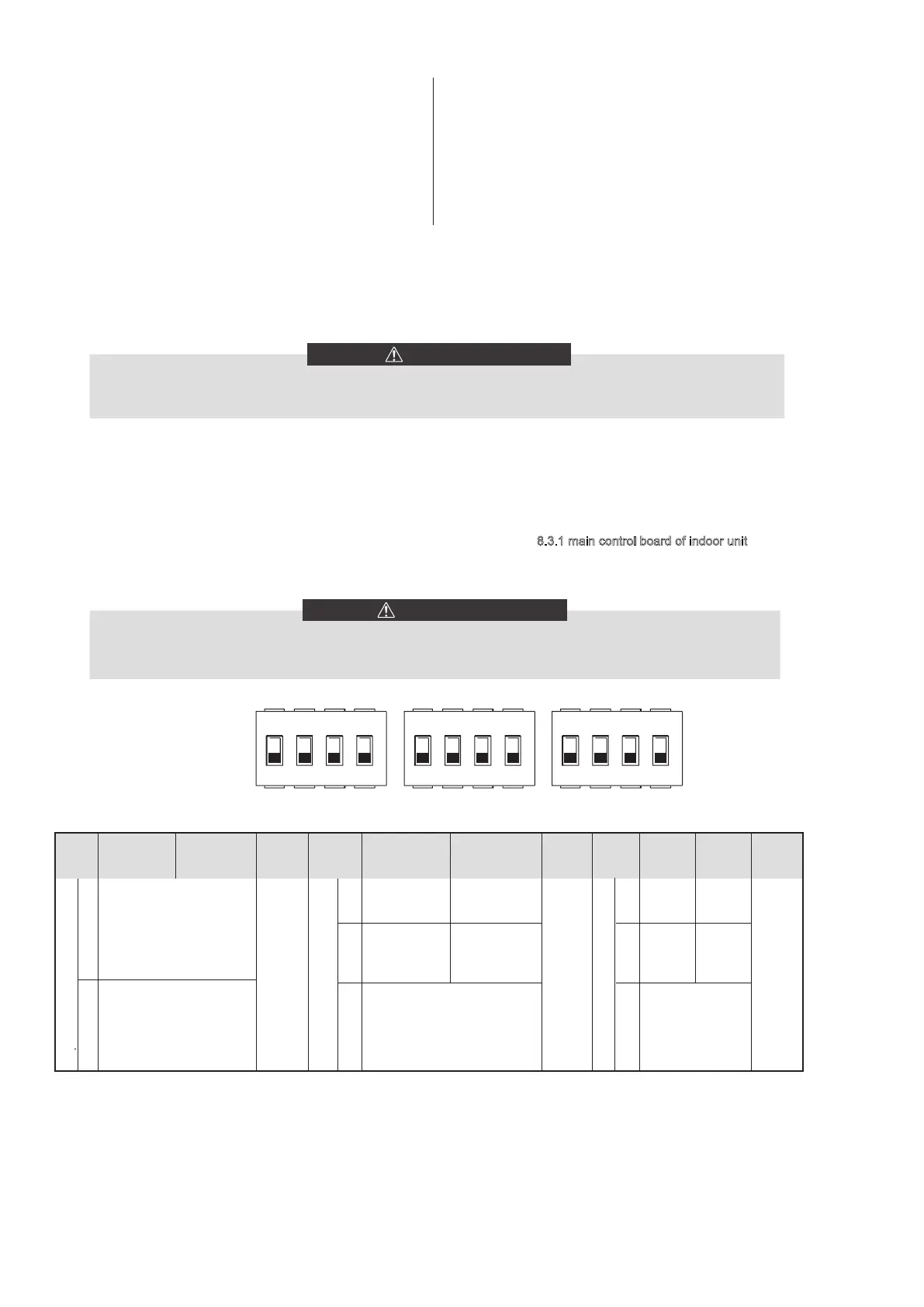
DIP switch S1、S2 and S4 is located on the indoor unit main control board (see "8.3.1 main control board of indoor unit") and
allows configuration of additional heating source thermistor installation, the second inner backup heater installation, etc.
Switch off the power supply before opening the switch box service panel and making any changes to the DIP switch
settings.
WARNING
9.1.1 Function setting
9.1 DIP switch settings overview
1 2 3 4 1 2 3 4
S1 S2
ONOFF
1 2 3 4
S4
1. when EVU signal is on, the unit operate as below:
DHW mode turn on, the setting temperature will be changed to 70℃
automatically, and the TBH operate as below:T5<69. the TBH is on,
T5 ≥ 70, the
TBH is off. The unit operate in cooling/heating mode
as the normal logic.
2.
When EVU signal is off, and SG signal is on, the unit
operate
normally.
3. When EVU signal is off, SG signal is off, the DHW mode is off, and
the
TBH is invalid, disinfect function is invalid. The max running time
for
cooling/heating is "SG RUNNIN TIME", then unit will be off.
ON=1 OFF=0
1/2
2
DIP
switch
0/0=Without IBH and AHS
1/0=With IBH
0/1=With AHS for heat mode
1/1=With AHS for heat mode
and DHW mode
3/4
1
3/4
ON=1
OFF=0
DIP
switch
S1 S2
Factory
defaluts
Refer to
eletrically
controlled
wiring
diagram
Start pumpo after
six hours will
be invalid
Factory
defaluts
without TBH with TBH
Start pumpo after
six hours will
be valid
DIP
switch
S4
1
2
3/4
Factory
defaluts
ON=1 OFF=0
Reserved Reserved
Reserved
Reserved
Reserved
0/0=IBH(One-step
control)
0/1=IBH(Two-step
control)
1/1=IBH(Three-step
control)
0/0=pump 1
0/1=pump 2
1/0=pump 3
1/1=pump 4
Refer to
eletrically
controlled
wiring
diagram
Refer to
eletrically
controlled
wiring
diagram