8
4111-0014 — Apr. 2020
©
2020 Systems, LLC
PowerStop vehicle restraints are available in the
following models and options:
PowerStop M
Mechanical PowerStop
PowerStop MML
Mechanical PowerStop
Manual Inside and Outside Lights
PowerStop MAL
Mechanical PowerStop
Automatic Inside and Outside Lights
PowerStop AAL
Automatic PowerStop
Automatic Inside and Outside Lights
Note:
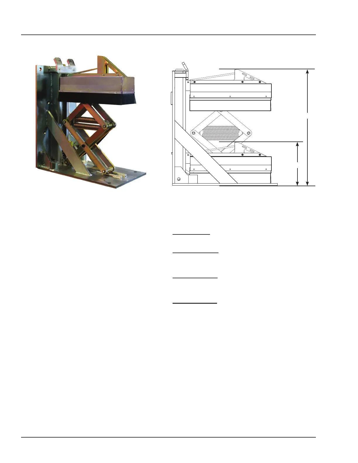
• All PowerStop models with the standard single
level tall restraint hook have a service range of 12”
to 29-1/4” (304.8 mm to 742.95 mm). See Figure 5.
• With the optional Low Profile restraint hook, the
service range is 10” to 27-1/2” (254 mm to 698.5
mm).
• Consult the factory for operating range information
for sloped approaches.
Call Systems, LLC to discuss available options to
meet your specific needs.
29 1/4”
12”
INTRODUCTION
TOLERANCES
(UNLESS OTHERWISE NOTED)
FRACTIONAL:
1/32"
DECIMAL:
.00 =
.01"
.000 =
.005"
ANGULAR:
1
DRAWN BY
CHECKED BY
DRAWING NO.
DATE
BDK 1/22/2020
S Y S T E M S
L o a d i n g D o c k E q u i p m e n t
P O W E R A M P
M C G U I R E
D L M
This print is the property of Systems, LLC and represents a proprietary article in which Systems, LLC retains any and all patent and other rights, including exclusive rights
of use and/or manufacture and/or sale. Possession of this print does not convey any permission to reproduce, print or manufactu
re the article or articles shown therein,
such permission to be granted only by written authorization signed by an officer or other authorized agent of Systems, LLC thereof.
MATERIAL
STOCK NO.
9415-0062
FINAL ASM - PSTOP/STOPTITE 2018
REV A - ECN 18-066
Technical Service at 800-643-5424 or techservices@loadingdocksystems.com
This manual provides current information on the
PowerStop vehicle restraint (Figure 4). Due to
ongoing product improvement, some parts may have
changed, along with operation and troubleshooting
methods. This manual describes these changes
where applicable.
The PowerStop is a non-impact, self-aligning truck
restraining system with restraining force in excess of
32,000 lbs.
PowerStop Mechanical models are manually operated
with an operating wand. The PowerStop Automatic
(hydraulic) comes equipped with an electrical
control panel, which allows push button operation
of the vehicle restraint functions. When combining a
Poweramp Dock Leveler with a PowerStop Automatic
vehicle restraint, the control panel will allow for
operation of both units in the same control panel.
Each PowerStop vehicle restraint unit and control
panel (if equipped) has been factory tested to ensure
satisfactory operation.
To illustrate which connections are to be made in the
field at installation, electrical drawings are included
with each order or by contacting Systems, LLC
Technical Services.
General Information
Figure 4
Figure 5



 To Next Page