-31-
15. RELAY OUTPUT
Terminal Designation Terminal description
MODE Mode selection rotary switch. Used to show and congure mode of operation for relay.
LED1 / LINK Slowly blinking when module is powered, permanently lid when link established
7
.
LED2 / ACT
Flashing yellow when data reception detected. Combined (OR)
with Modbus & BACnet data reception indication
7
.
NC Normally closed relay contact. Opens when relay is active.
C Relay common contact.
NO / OK Normally open relay contact. Closes when relay is active.
NOTE: VR25-H, VR30-M and VR30-H have one status relay, used to signal pump operation or malfunction.
All other models have two relays. See table following for functionality.
The communications module has a built in web server which allows you to access your pump directly from an existing
Ethernet network. Direct connection to a computer is also possible with a crossover cable.
The web server uses HTML pages to set/view:
• Regulation mode settings
• Regulation parameters (power, RPM, head, ow, eciency)
• Relay settings
• External control inputs
• Current and previews error
• Pump statistics (power consumption, run time and other).
7
When Mode 6 or Mode 7 is selected, LED1 and LED2 will show relay conguration. See section “4.3 Module mode selection”
LED is on
LED is o
16. NETWORK
Terminal Designation Terminal description
MODE Can be used to reset network conguration
LED1 / LINK Slowly blinking when module is powered, permanently lid when link established.
Ethernet 10BASE-T RJ-45 connector.
LED2 / ACT Indicates Ethernet activity or Modbus reception.
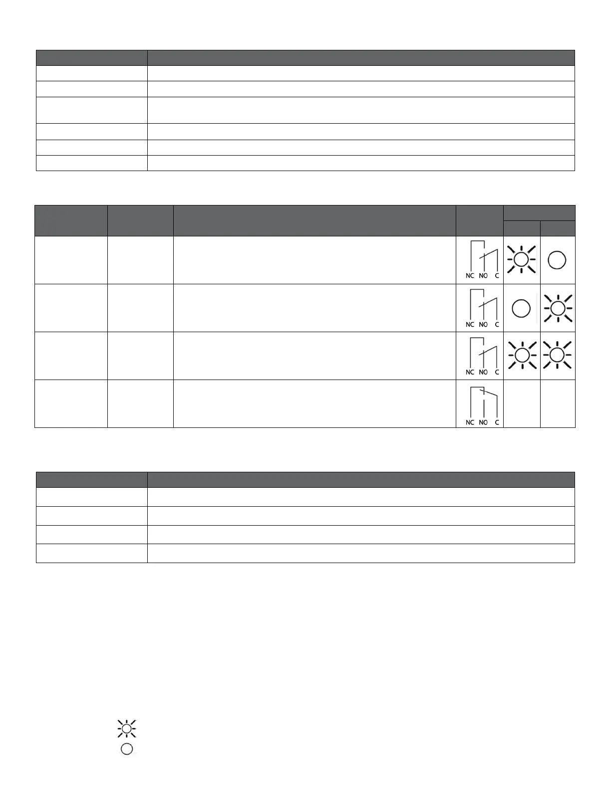
Relay
Conguration
Output
Status
Description
Relay
Position
LED status
7
LED 1 LED 2
0
Error
[default]
Only active when the pump is powered up and
detects a problem with operation.
1 Ready
The relay signal is active when the pump
is ready for operation.
2 Operation
The relay signal is active as long as the pump is operating. If the
pump comes to a stop or an error occurs, relay will deactivate.
--- --- Relay output not active.
Relay conguration number can be modied by either the web interface, Modbus register 012 (relay 1), 17 (relay 2 where applicable) or the Mode switch.
 Loading...