-43-
18. MODBUS
18.1 Modbus Related Interface
Terminal Designation Terminal Description
MODE Can be used to reset network conguration.
LED2 / ACT Indicates Ethernet activity or Modbus reception.
B/D- RS-485 negative data signal for Modbus.
A/D+ RS-485 positive data signal for Modbus.
COM/0V RS-485 common and analog input common (ground).
18.2 Modbus Topology
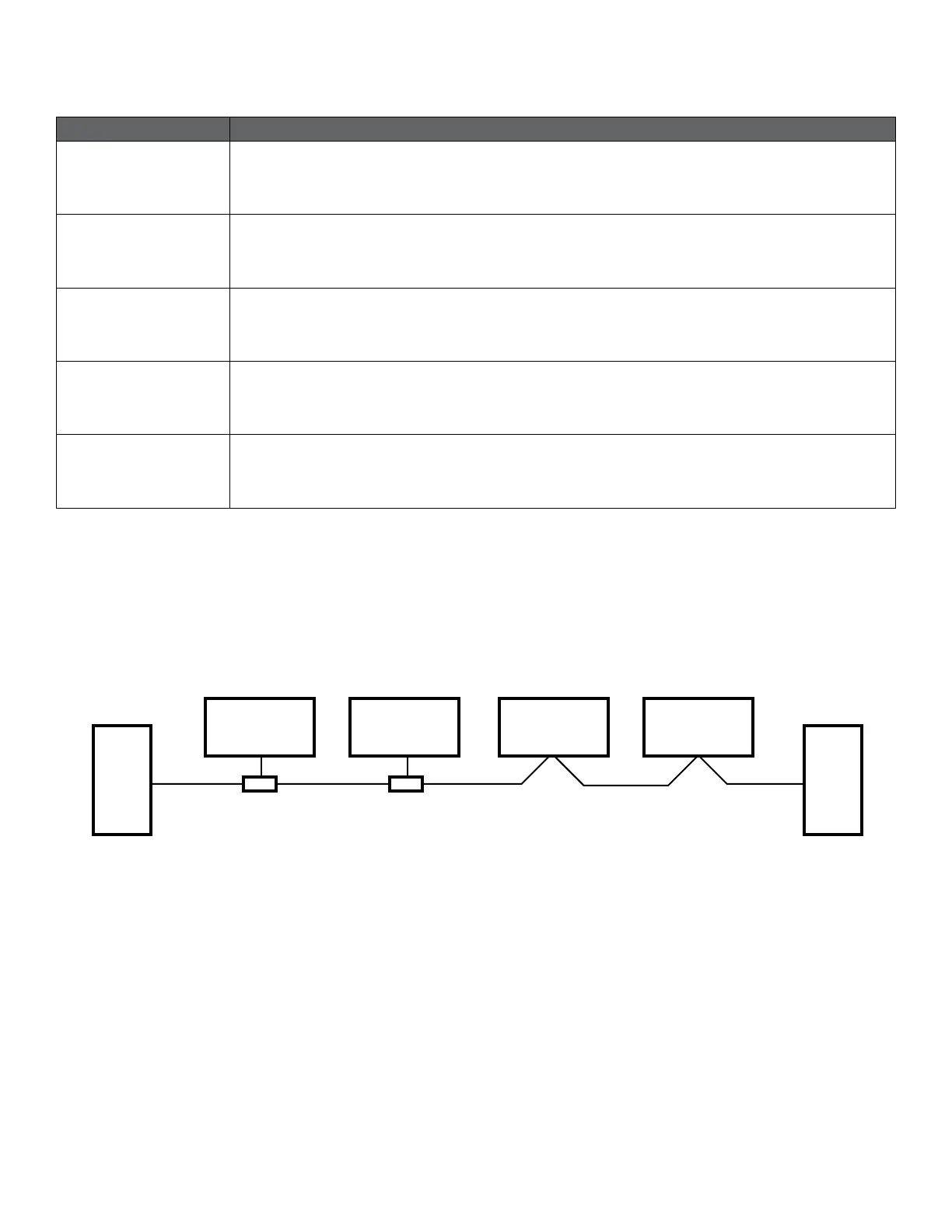
The VR Control is a Modbus lag, connected directly to a Modbus RTU network. Connection can be made in either daisy
chain style (if cabling allows such a connection) or a limited length passive tap. Schematic example is in Figure 6.
Figure 6: Example of Modbus network
Typically, only one Lead pump device is connected to the serial bus, and one or several lags are also connected to the
bus. Lags do not communicate with each other and will never transmit data without receiving a proper request from
the master device.
Up to 32 single load devices can be connected to one RS-485 Modbus system without using a repeater. As this module
is a 1/8 load device, up to 256 modules can be connected to the bus. Repeaters can be used to extend the maximum
transmission distance and increase device count if needed.
Lag 1 Lead Pump Lag 2 Lag 3
Line
Termination
Line
Termination
Passive tap Daisy chain
 Loading...