-47-
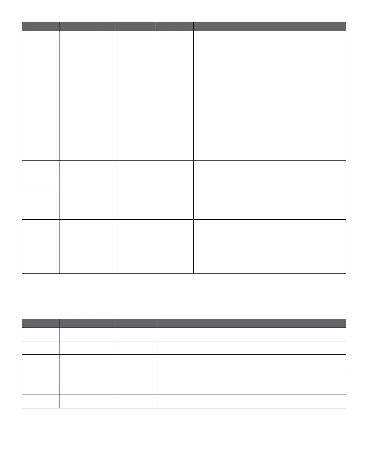
Address Register name Range Resolution Description
014 SET1Type --- 1
Conguration for SET1 terminal.
0 = “NO FUNCTION”
1 = “RUN input 2-3V”
2 = “MAX input 0-10V”
3 = “MAX input 2-10V”
4 = “RUN input 4-6mA”
5 = “MAX input 0-20mA”
6 = “MAX input 4-20mA”
7 = “FB output 10.5V”
8 = “FLOW output 2-10V”
9 = “FLOW output 4-20mA”
10 = “RPM output 2-10V”
11 = “RPM output 4-20mA”
12 = “ERROR output 10-0V”
13 = “ERROR output 20-0mA”
14 = “PWM SOLAR input”
15 = “PWM HEATING input”
16 = “PWM FLOW+ERR output”
015 SET2Type --- 1
Conguration for SET2 terminal.
See enumeration for register 014
016 SET3Type --- 1
Stop bits used for communication. 2 stop
bits will only be used when “Parity” is set to 0.
1 = 1 stop bit [default]
2 = 2 stop bits
017 Relay2Control 0..2 1
Congures module relay output.
0 = indicates fault
1 = indicates pump ready
2 = indicates pump operation
See section “Error! Reference source not found. Error!
Reference source not found.”
VR status registers
Registers in this block are read with either function codes 0x03 or 0x04. They are read-only.
This block can be used for various kinds of fault nding.
Address Register name Resolution Description
021..022 RESERVED --- ---
023 Software Version 0.1 Module software version
024..029 RESERVED --- ---
030 Product Version 1 Product version [32x for module, x denotes hardware revision]
031 RESERVED --- ---
032 Software Version 0.1 Module software version[10 = 1.0]
 Loading...