8.10.2
T2000-A450X CTCSS & Scrambler Kit
M2000-00
31/12/97 Copyright TEL
8.10.1 Components Required
The T2000-A450X kits contain the following components:
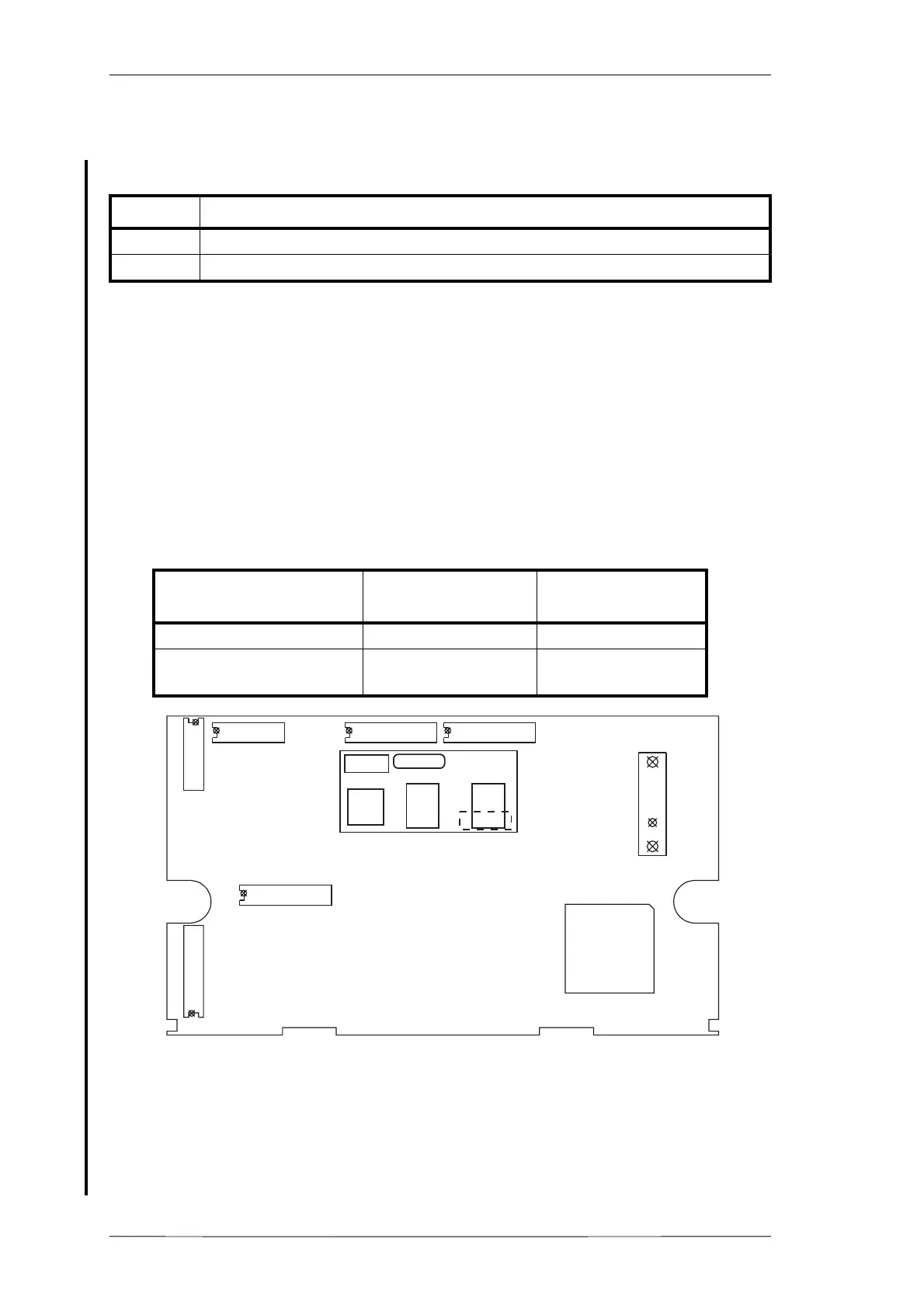
8.10.2 Fitting
1 Refer to Figure 8.10.1.
Remove the top cover of the radio by unscrewing the four cover screws, unscrew
the logic PCB and fold out.
2 Select the T2000-A450X link options, as described in Section 8.10.3, “T2000-A450X
Link Options”.
Position the T2000-A450X PCB as shown, and plug into the connector on the
T2000 logic PCB:
Figure 8.10.1 T2000-A450X PCB Mounting (T201X logic PCB shown)
2 Position the foam tape provided on top of #IC5, on the T2000-A450X PCB.
3 Carefully fold the logic PCB back in position and secure using the three logic PCB
retaining screws.
Refit the top cover.
Quantity Description
1 T2000-A450X PCB assembly
12mm PVC foam tape
Model PCB IPN
Connector Circuit
Reference
T2010 & T2015 220-01377-01 or later P2
T2020, T203X, T2040 &
T2050
220-01344-02 or later #T3K45
SK505
S8
S3
S2
S15
S14
S13
S1
P2
P1
T2000-45
P2
 Loading...