M2000-00
T2000-A450X CTCSS & Scrambler Kit
8.10.3
Copyright TEL 31/12/97
8.10.3 T2000-A450X Link Options
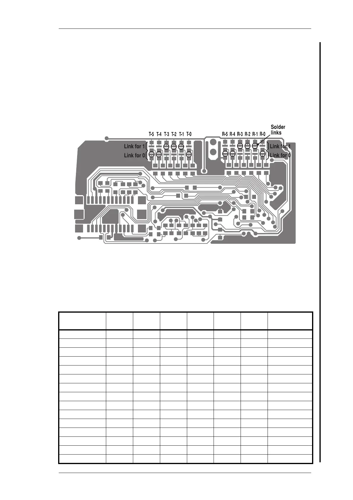
There are 2 groups of links on the underside of the T2000-A4500 PCB, the receive
(R) group and the transmit (T) group. Each group contains 6 bits that are pulled
logic high or low, by either solder links or zero ohm resistors.
The receive settings are set by links R-0 to R-5 and the transmit settings by links T-
0 to T-5. A short to the 5V line represents a ‘1’, and a short to ground represents a
‘0’.
The following diagram shows the T2000-A450X PCB, with links indicated.
T2000-A4500 CTCSS PCB Links
The following table gives the linking details for the 38 independent transmit and receive
CTCSS frequencies.
Ton e Nu m ber
R-5
T-5
R-4
T-4
R-3
T-3
R-2
T-2
R-1
T-1
R-0
T-0
CTCSS
Frequency (Hz)
1 000000 67
2 000001 71.9
3 000010 74.4
4 000011 77
5 000100 79.7
6 000101 82.5
7 000110 85.4
8 000111 88.5
9 001000 91.5
10 001001 94.8
11 001010 97.4
12 001011 100
13 001100 103.5
14 001101 107.2
15 001110 110.9
T2000-A450X PCB IPN 220-01335-04 (bottom side):
links for transmit & receive 110.9Hz CTCSS frequency shown.
 Loading...