M850-00
T856/857 Functional Testing
C4.1
Copyright TEL 31/09/98
4 T856/857 Functional Testing
Caution:
This equipment contains CMOS devices which are susceptible to dam-
age from static charges. Refer to Section 1.2 in Part A for more infor-
mation on anti-static procedures when handling these devices.
The following test procedures will confirm that the T856/857 has been tuned and
adjusted correctly and is fully operational.
Note 1:
In this and following sections deviation settings are given first for wide
bandwidth sets, followed by settings in brackets for mid bandwidth sets ( )
and narrow bandwidth sets [ ].
Note 2:
Unless otherwise specified, the term "PGM800Win" used in this and follow-
ing sections refers to version 2.00 and later of the software.
Refer to Figure 4.4 and Figure 4.5 for the location of the main tuning and adjustment
controls, and to Section 3.3 for the test equipment set-up. Refer also to Section 6 where
the parts lists, grid reference index and diagrams will provide detailed information on
identifying and locating components and test points on the main PCB. The parts list
and diagrams for the VCO PCB are in Part E.
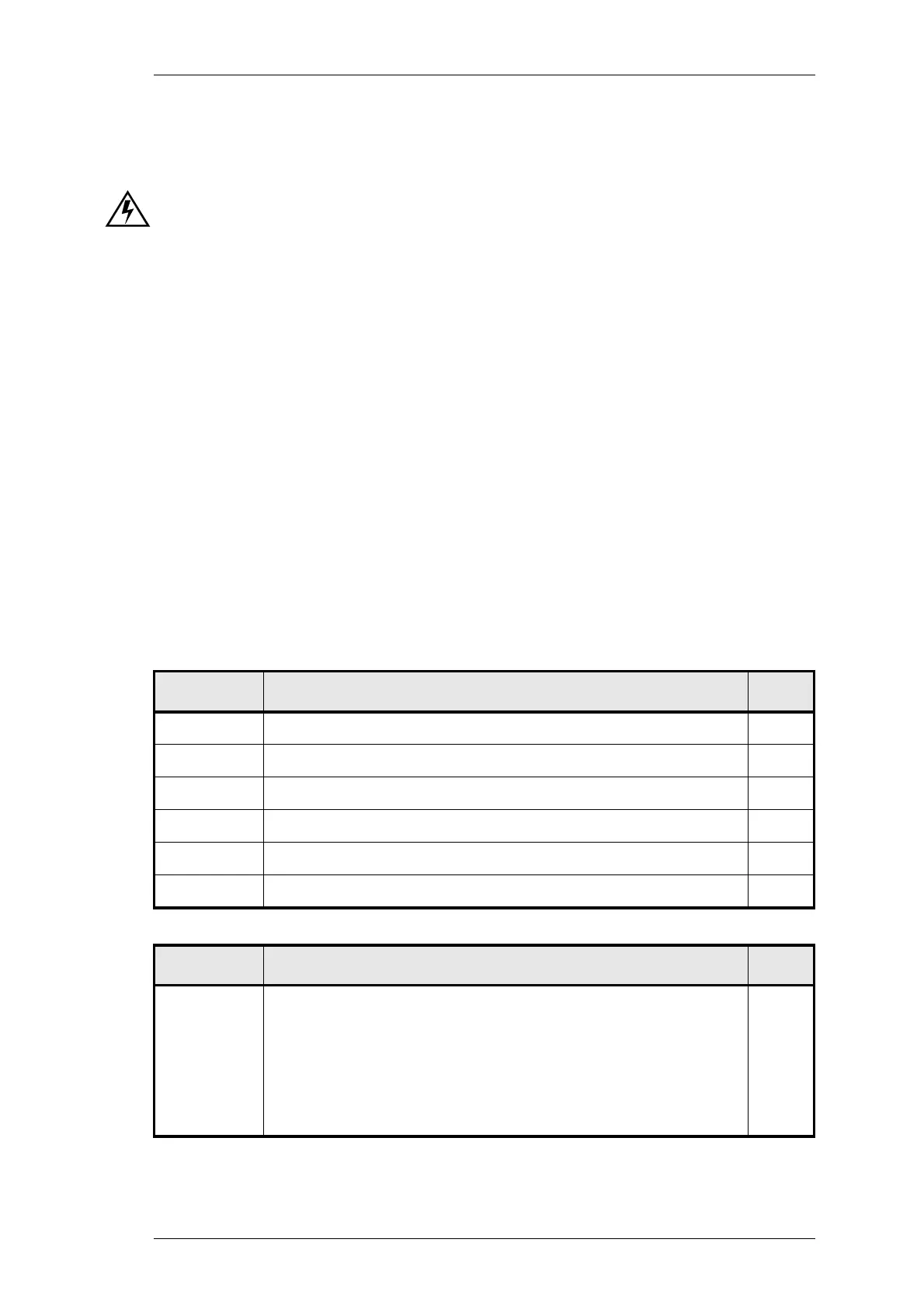
The following topics are covered in this section.
Section Title Page
4.1 Current Consumption 4.3
4.2 Output Power 4.3
4.3 Output Frequency 4.3
4.4 Timers 4.3
4.5 Frequency Response 4.4
4.6 Audio Level Input Sensitivity 4.7
Figure Title Page
4.1
4.2
4.3
4.4
4.5
T856/857 Transmit Timers
T856/857 Pre-emphasis Response
T856/857 Limiting Response
T856 Main Tuning & Adjustment Controls
T857 Main Tuning & Adjustment Controls
4.4
4.5
4.6
4.9
4.11
 Loading...


