M850-00
T856/857 Fault Finding
C5.5
Copyright TEL 31/09/98
5.5 RF Checks
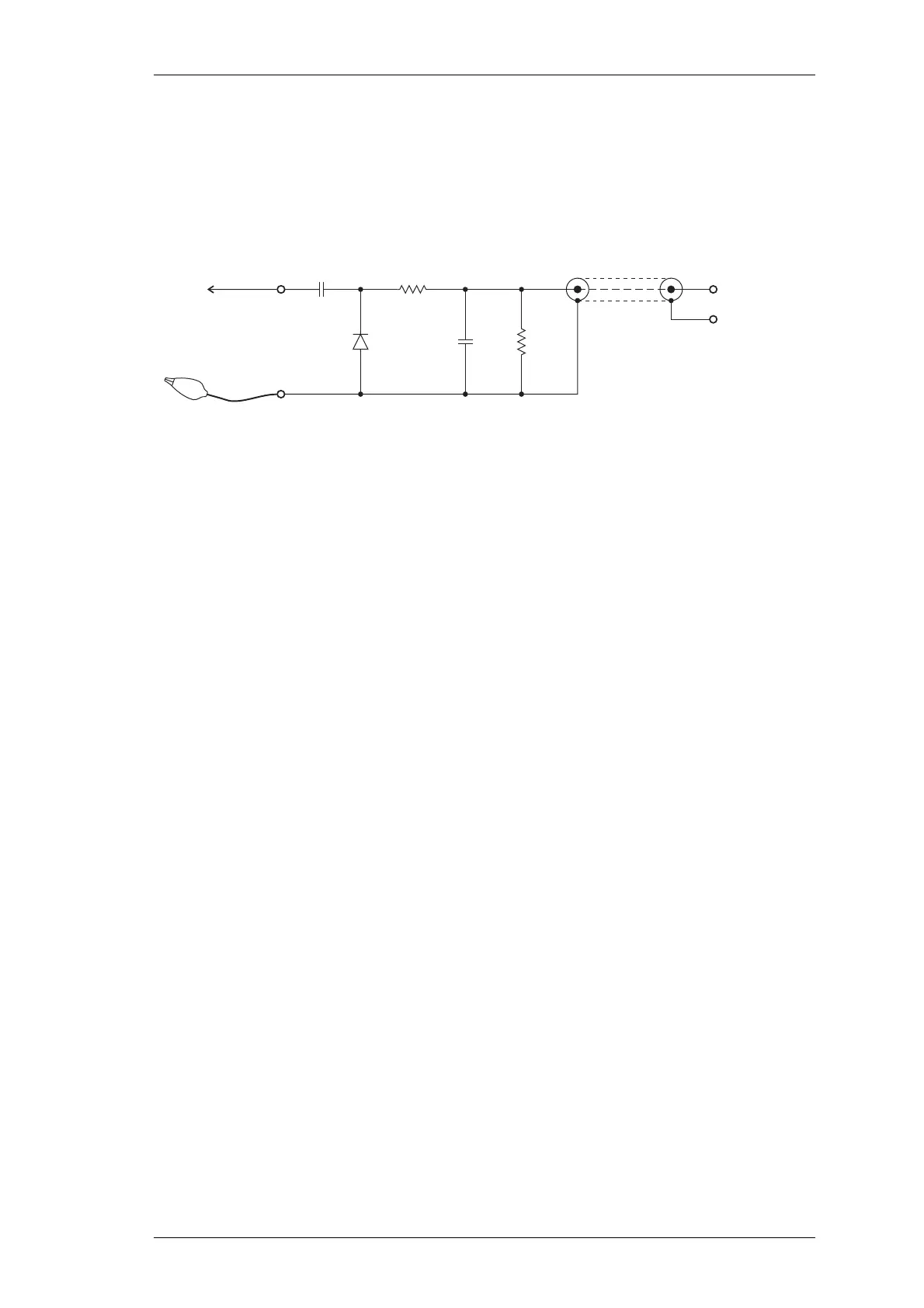
In-circuit RF levels may be measured with an RF probe on which the earth lead has been
shortened to a minimum (i.e. 13mm). Refer to the circuit diagrams for typical levels.
Figure 5.1 shows a suitable RF probe circuit..
Figure 5.1 RF Diode Probe Circuit
5.5.1 T856 Drive Power
Refer to the drive amplifier fault finding chart (Section 5.7.4).
Ensure that the VCO locks (refer to Section 5.4.2).
Connect the drive output to a power meter and key the transmitter.
Check that the exciter output power (SK310) is >1.5W.
Note:
If the synthesiser is out of lock, the lock detector (synthesiser IC740 and
comparator IC750) will prevent the RF signal from reaching the PA by
switching the supply to the exciter amplifier (Q350, Q355).
5.5.2 T856 PA Output Power
Reconnect the drive output to the PA input.
Connect the PA to a power meter and key the transmitter.
Check that the output power is >30W with RV310 (power control) adjusted fully
clockwise.
5.5.3 T857 Output Power
Refer to the exciter drive amplifier fault finding chart (Section 5.7.6).
Ensure that the VCO locks (refer to Section 5.4.2).
100k
10k
1n
1n
1N6263
Coax
Probe
Earthing Clip
DC to DVM or
Oscilloscope
This unit is not suitable for use on high power RF circuits.
 Loading...


