M850-00
T858/859 Initial Adjustment
D3.3
Copyright TEL 31/09/98
3.1 Test Equipment Required
• DC power supply capable of delivering the following at 13.8V:
T858 >16A (e.g. Tait T807)
T859 >25A (e.g. Tait T808).
• Multimeter or DMM (e.g. Fluke 77).
• RF power meter (e.g. HP 435 series or Bird Wattmeter).
• 250W 30dB 50 ohm pad (e.g. Weinschel 40-20-34), or other suitable load.
• 300W 3dB 50 ohm pad (e.g. Weinschel 40-3-34).
• 'BNC' to 'N' type adaptors (e.g. Amphenol, Greenpar).
• Appropriate trimming tools.
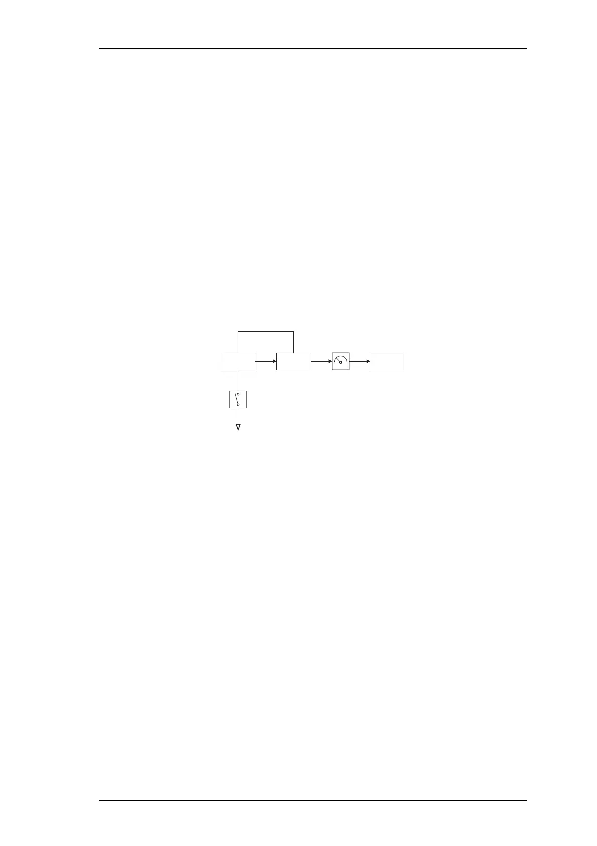
Figure 3.1 T858/859 Test Equipment Set-up
3.2 Preliminary Checks
Check for short circuits between the positive rail and earth.
Set up the test equipment as in Figure 3.1.
Connect the T858/859 to a 13.8V DC supply.
Check that the quiescent current is approximately 45mA.
To key the transmitter, earth the key line (D-range 1 pin 13) on the exciter.
Check that the power supply is still at 13.8V under load.
Check that the regulated power control supply is approximately 7V (pin 1 of IC2).
Note:
The output power and alarm levels should be set with the cover shield on.
If the cover is removed for other adjustment procedures, make a final check
of the output power and alarm levels with the cover shield on.
Exciter PA Load
Tx Key
RF Power
Meter
Tx Enable
 Loading...


