TBA0STU/TBA0STP CTU Operation Manual Using the CTU with a TB9100 31
© Tait Electronics Limited September 2005
600Ω LOAD
This switch connects or disconnects the 600Ω load across the LINE
OUTPUT. This allows the output to be terminated correctly for calibration
procedures. Turn the switch on if the LINE OUTPUT socket is not
otherwise terminated.
SYSTEM INTERFACE The RJ45 connector is used for the analog line and the 9-way connector is
used for digital I/O. Connect the RJ45 to the RJ45 AUD connector on the
reciter and the 9-way connector to the 9-way DIG connector on the reciter.
SYSTEM INTERFACE Not used with TB9100.
DIGITAL/
PROGRAMMING
INPUTS
These switches let you set the digital inputs into the TB9100 high or low.
Only the first four are used with TB9100. These switches are connected to
the digital input lines on the 9-way system interface connector. Digital
inputs can be used for external channel selection. Refer to the Customer
Service Software documentation for details on how to configure this.
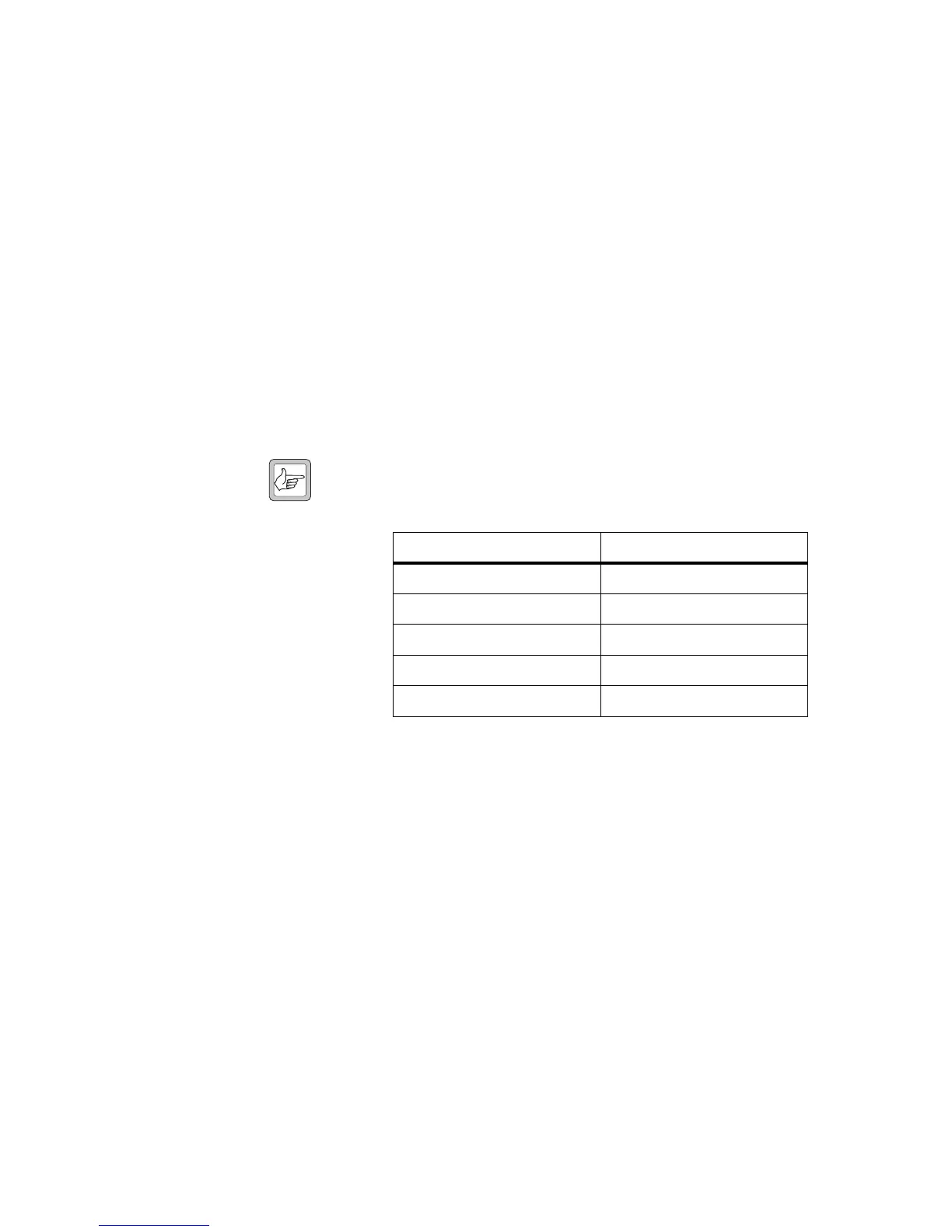
Note The TB9100 digital inputs are numbered 0 to 4 on the CSS,
which correspond to digital inputs 1 to 4 and TX RELAY on the
CTU.
Set the switch to position “1” to set the digital input high. Set the switch to
position “0” to set the digital input low.
Speaker The CTU is fitted with a 0.5W 16Ω speaker. Audio from LINE OUTPUT
can be connected to this speaker.
VOLUME This controls the volume of the speaker. Rotate clockwise to increase the
volume, and anticlockwise to decrease the volume.
RSSI This banana socket is used as digital output 0 by the TB9100.
DIGITAL OUTPUTS Not used with TB9100.
j
1)
1!
1@
TB9100 Digital Input CTU Digital Input
0Switch 1
1Switch 2
2Switch 3
3Switch 4
4 TX RELAY (see
1*)
1#
1$
1%
1^
 Loading...


