TBA0STU/TBA0STP CTU Operation Manual Appendix A - CTU Accessories 37
© Tait Electronics Limited September 2005
Using a PMU to
Power the CTU
The CTU can be powered from the auxiliary DC output at the rear of the
PMU
1
. Connect the CTU to the PMU using one of the supplied DC
power cables
j fitted with the supplied power connector f (as shown in
Figure A.1).
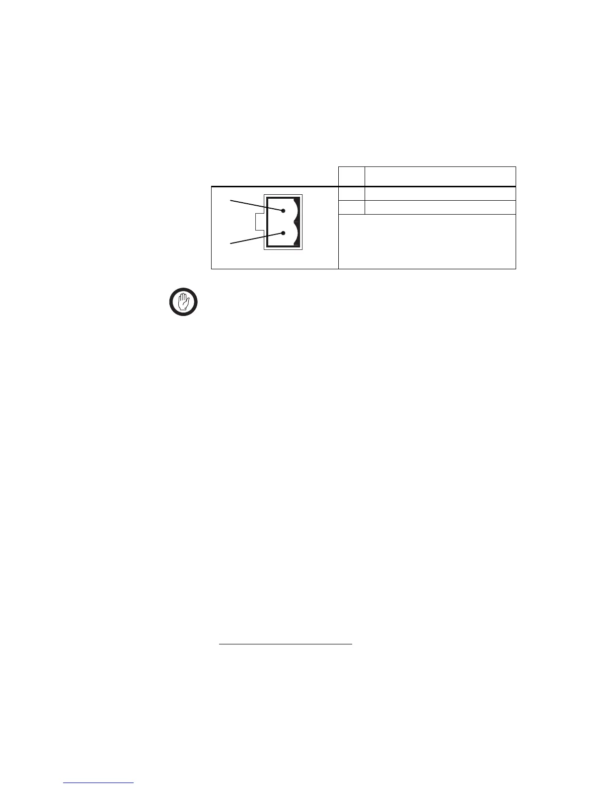
The pin allocations for the 2-way auxiliary DC output connector on the
PMU
2
are given in the following table.
Important Do not power the CTU from a PMU fitted with a 48V
auxiliary power supply board. The maximum supply volt-
age for the CTU is 32VDC. Use either a PMU 12VDC or
24VDC auxiliary output, or an external power supply.
Note that the auxiliary output can be supplied to the CTU
via the system interface connector on the reciter if the aux-
iliary DC power cable is fitted, as well as via a direct con-
nection to the PMU auxiliary output.
1. The PMU must be fitted with an optional auxiliary power supply board.
2. This type of connector is fitted to PMUs manufactured from August 2004
onwards .
Pin Description
1 +V output
2 ground
2-way connector - external view
b
c
 Loading...


