40 Appendix B - CTU Block Diagram TBA0STU/TBA0STP CTU Operation Manual
© Tait Electronics Limited September 2005
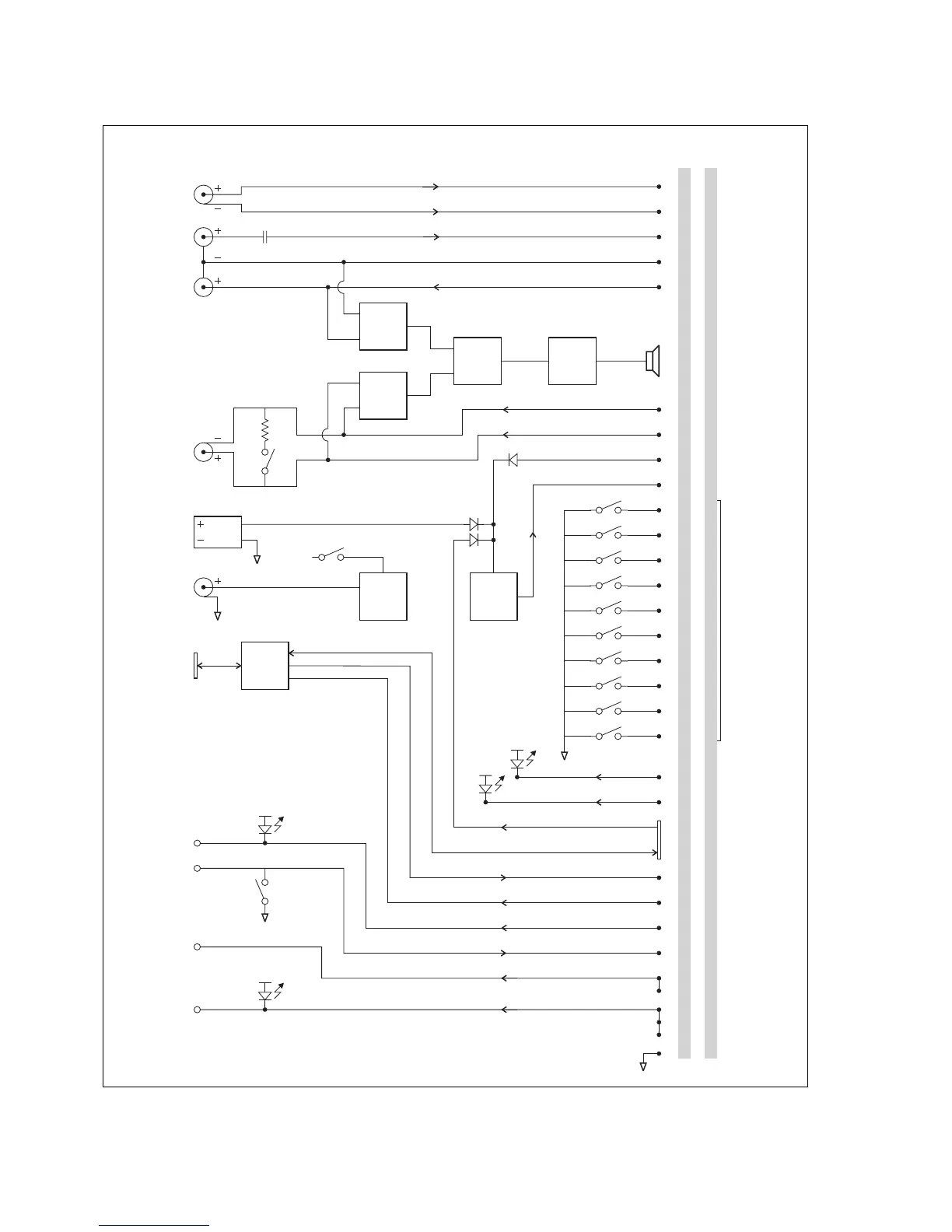
Figure B.1 CTU Block Diagram
Power
Supply
Noise
Source
Buffer
600Ω
ON
OFF
ON
OFF
ON
OFF
ON
OFF
ON
OFF
ON
OFF
ON
OFF
ON
OFF
ON
OFF
ON
OFF
14 14 4
6
7
8
15
16
17
18
19
20
21
22
23
11 12
12 13
10
System
Control Bus
Rx Gate Output
Tx Data Output
Rx Data Input
Tx Key Input**
RSSI Output
Tx Relay Output
Ground
94 7
2
3
2
10 5
9
1
8
24
25 15 5 8
1
2
3
4
5
6
7
8
9
10
22 4
3
3
3
4
56
78
6
25 15 9 RJ
75
6
11
13 9
1
Speaker
Amplifier
Speaker
Switch
High
Impedance
Buffer
High
Impedance
Buffer
+V
+V
+V
+V
Balanced
Line Input
Unbalanced
Line Input
Unbalanced
Line Output
Balanced
Line Output
Noise Source
Output
Programming
Port
Rx Gate Output
Tx Key Input
RSSI Output
Tx Relay Output
DC Input
Tx Line +
Tx Line –
Tx Audio
Rx Audio
Rx Line –
Rx Line +
+8V Supply**
+8V
+AUX_V Output
Digital Output 1
Digital Output 2
Digital Inputs
Digital Output 3
Digital Input 4
Digital Output 0
Audio Ground
System Interface Connector
Pin Allocations*
CTU Inputs
& Outputs
OFF
ON
+V
OFF
ON
*25 = 25-way D-range, 15 = 15-way D-range,
9 = 9-way D-range, RJ = RJ45
* +8V Supply and Tx Key Input work in conjunction to
provide the TB9100 channel seize input. Together
they serve the “E” function of the E&M interface.
*
 Loading...


