TB7100 Installation Guide Connections 17
© Tait Electronics Limited March 2006
2 Connections
Overview This section gives an overview of looms and cables, and describes the
specifications and pinouts of the external and internal connectors.
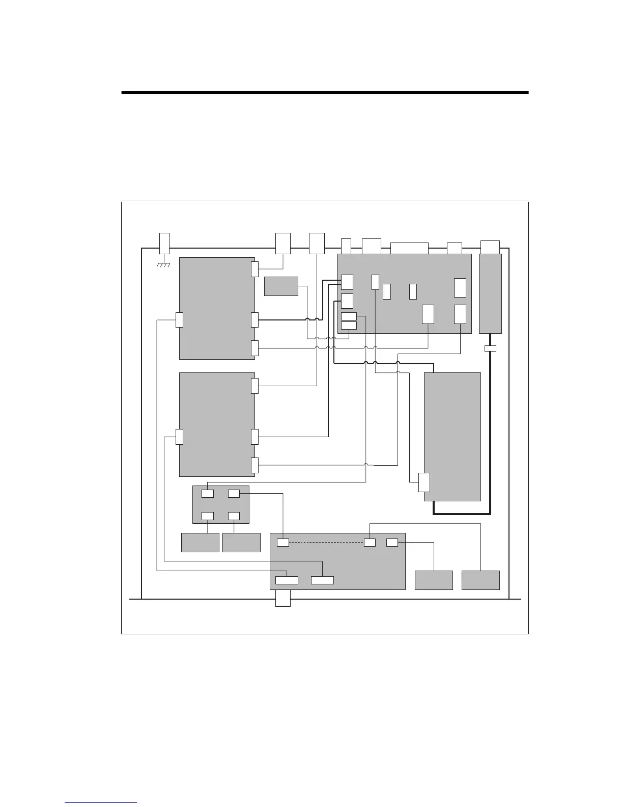
Figure 2.1 provides an overview of the connections.
For information on the factory connector and the internal options
connector of the transmitter and receiver, refer to the PCB information.
Figure 2.1 Connectors, looms and cables
DC Input
Connector
System
Connector
Serial Data
Connector
AC Input
Connector
Rx
Connector
Tx/Ant
Connector
Ground
Point
Transmitter
Module
UI Board
AC
Power Supply
Unit
Fan
FanFan
Fan Power Board
Speaker
Temperature
Sensor
Prog/Mic
Connector
Receiver/SI
DC power
RF
Transmitter/SI
RF
Receiver/UI
Transmitter/UI
AC Input Filter
Module
SI Board
Fuse
Mains fail signal
SK100
PL100
SK101
SK103
SK100
PL100
SK101
SK103
RF connector
DC power
connector
Auxiliary
connector
User interface
connector
Receiver
Module
RF connector
DC power
connector
Auxiliary
connector
User interface
connector
J102
J103
J105
J106 J104
J201
J200
J110
J100
J202
J101
DC power
Fan power
SK1
SK3
SK2
PL2PL7PL8
PL4
PL3
PL5
PL6
Factory
only
PL101
J600
DC Output
AC power
J109
Relay Driver
Configuration with internal AC power supply unit shown