18 Installing the Radio TM9100 Mobiles: 110 W Mobile Installation Guide
© Tait Electronics Limited October 2005
4.7 Connecting a Remote Speaker
If a high-power remote speaker is required, Tait recommends using:
■ TMAA10-03 high-power remote speaker for 25W radios.
Installation instructions (IPN 402-00010-00) are provided with the speaker.
If a different speaker is used, receptacles for the speaker pins of the power
connector are provided with the installation kit.
1. Run the speaker cable to the radio, then (underneath the RF
amplifier) alongside the ignition sense cable to the back of the radio
body.
2. Secure the speaker cable with cable ties using the small holes in the
side of the chassis (see Figure 4.3 on page 17), as was done for the
ignition sense cable.
3. Connect the speaker to pins 2 (SPK–) and 3 (SPK+) of the radio
body’s power connector (see Table 4.1).
4.8 Connecting to an Emergency Switch and/or
External Alert Devices
The auxiliary connector can be used to connect external devices and signals
that are typically connected to a radio. These devices and signals include:
■ an emergency switch to power up the radio (if required) and then enter
emergency mode
■ external alert devices.
If you want to connect an external device or signal, first check Table 4.2 to
see whether the signal is already used by the 100W RF amplifier.
If the signal is available, disconnect the loom between the RF amplifier and
the radio body. Open up the auxiliary connector (DB15) and wire in the
desired signal.
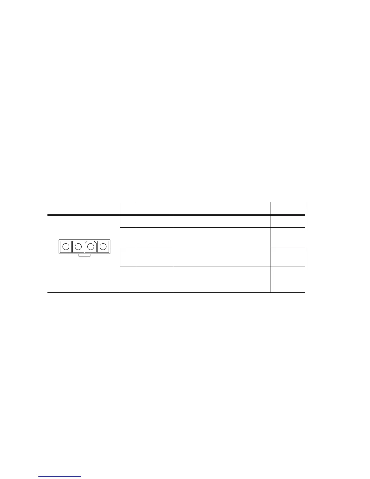
Table 4.1 Radio body power connector—pins and signals
Pinout Pin Signal name Description Signal type
1 AGND Earth return for radio body power source Ground
2 SPK– External speaker output. Balanced load
configuration
Analog
3 SPK+ External speaker output. Balanced load
configuration
Analog
4 13V8 BATT DC power input for radio body and
control head
Power
1 2 3 4
rear view