MAINTENANCE
MAINTENANCE
60 • On-Demand Water Heater Service Handbook for 240, 340 & 540 Condensing Models
Replacing the Heat
Exchanger
Tools:
#2 Phillips Screw Driver, 8” long
(a magnetic tip is helpful)
Pliers
Disconnect power by opening
the circuit breaker or removing
the fuses before installing or
servicing.
Use a non-contact circuit tester
to confirm that power is off
before working on or near any
electrical parts.
Ensure that the gas supply is
shut off at the manual gas
shutoff valve.
Replace the front cover after
servicing.
Failure to follow these warnings
can lead to personal injury or
death.
Consider removing the following
sections from this manual for easy
reference:
• “Component Diagrams/Item
Numbers” (starting on page 71).
• Figure 41 (p. 49) or Figure
42 (p. 50) which shows the
location of basic components.
This will allow you to lay the loose
pages beside this manual for easier
reference.
Also, screw sizes vary. We recommend
bagging and labeling screws as you
remove them, or reinstall them in
their proper places as you proceed
with disassembly. This will make
reassembly easier.
1. Shut the unit down as follows:
1.1 Shut O power and gas
supply as follows:
1.1.1
Shut o Power by
disconnecng the power
cord or shung o the
power disconnect.
1.1.2
Shut o the gas supply to the
water heater at the manual
gas shuto valve.
1.2
Drain the water from the
heater as follows:
1.2.1
Close the shuto valves on
the hot and cold side of the
heater.
1.2.2
IF isolaon valves are
installed: open up the drain
ports.
1.2.3
IF isolaon valves are not
installed: remove the lter
(item 406, page 74) and
open the pressure relief
valve.
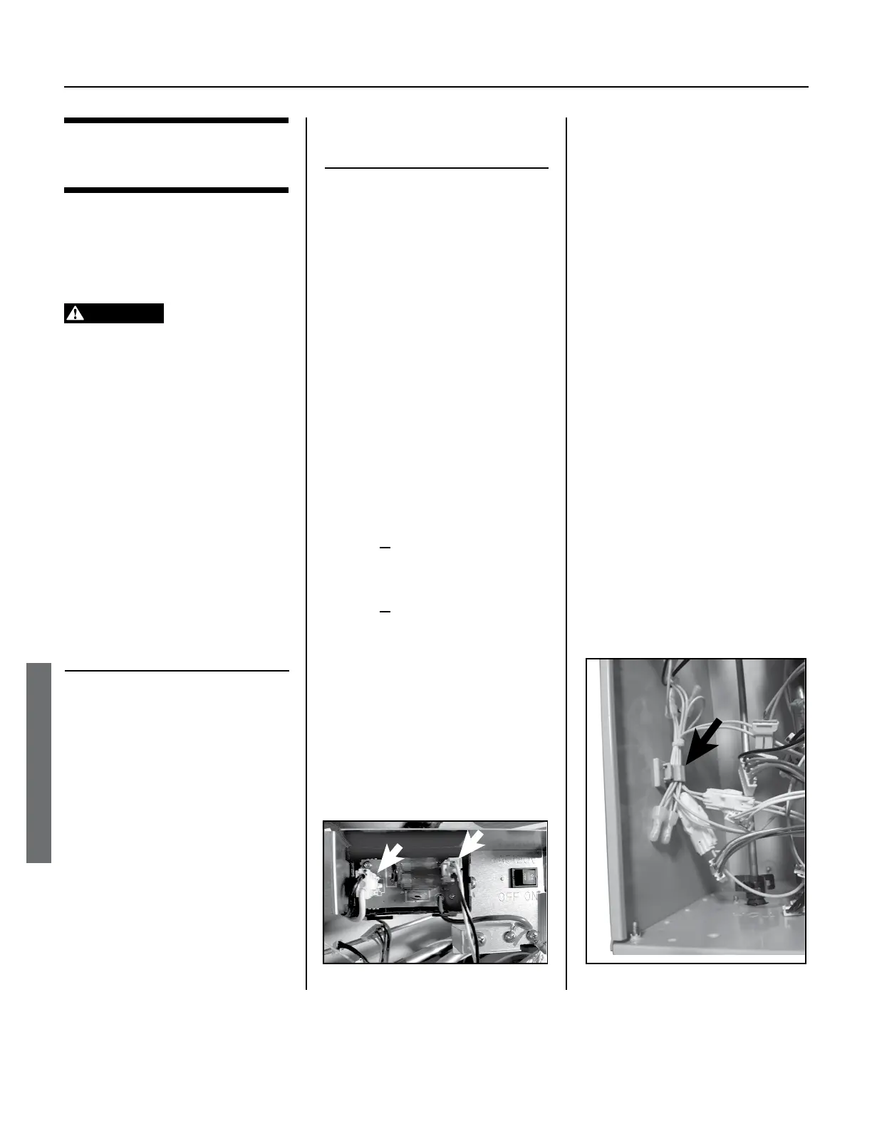
2. INDOOR MODELS: Remove the
Temperature Controller (item 722,
white connector that goes to the
computer board.
3. Remove the computer board as
follows (item 701, page 72; see
NOTICE:
•
During the next step, consider taking
a digital photo to aid in reassembly.
•
Do not touch the circuit board
components. Doing so may cause
damage by electrostatic discharge.
3.1 Disconnect all wire
connectors from the
computer board.
3.2
Remove the screw at the top of
the computer board assembly,
then remove the board. See
page 49 or 50, as
appropriate.
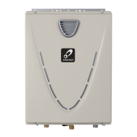
4. Remove the fuse box assembly
(item 703, page 72):
4.1 Disconnect both wire
connectors from the fuse
box ports (Figure 51).
Figure 52.
Figure 51.

 Loading...