MAINTENANCE
MAINTENANCE
On-Demand Water Heater Service Handbook for 240, 340 & 540 Condensing Models • 61
4.1 Open the clip that secures
the yellow wires to the
boom, le-hand side of the
cabinet. Remove the wires.
See Figure 52.
4.2
Remove both screws that
secure the fuse box and li
the fuse box away. (It will
sll be connected to wires.)
4.3
Unlatch the connectors on
the freeze protecon heater
wires. There are 5 sets of
these white connectors with
yellow wires (one above
the fuse box assembly,
three below the fuse box
assembly, and one near the
boom, right-hand side of
the cabinet).
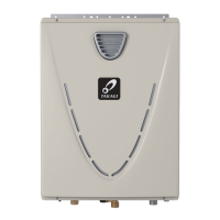
INDOOR MODELS ONLY:
The plug on the back of
the fuse box connects it
to the freeze protecon
thermostat. This thermostat
hangs o of the intake vent
(top, le of cabinet). Leave
that thermostat in place.
(See Figure 53.)
When you are finished, the
plug, wire, and fuse box will
hang from the intake vent.)
5.
valve (item 402, page 74) as
described in the following steps.
5.1 Remove fasteners 16A and
14-22 (items 460 and 461,
page 74).
NOTICE: If you have a 540
model with a bypass valve,
you must remove an
addional fastener. See item
458 at connecon point
(two places), page 74.
5.2
Pull the cold connecon
tube (item 466, page 74)
from the outlet of the ow
sensor/control valve.
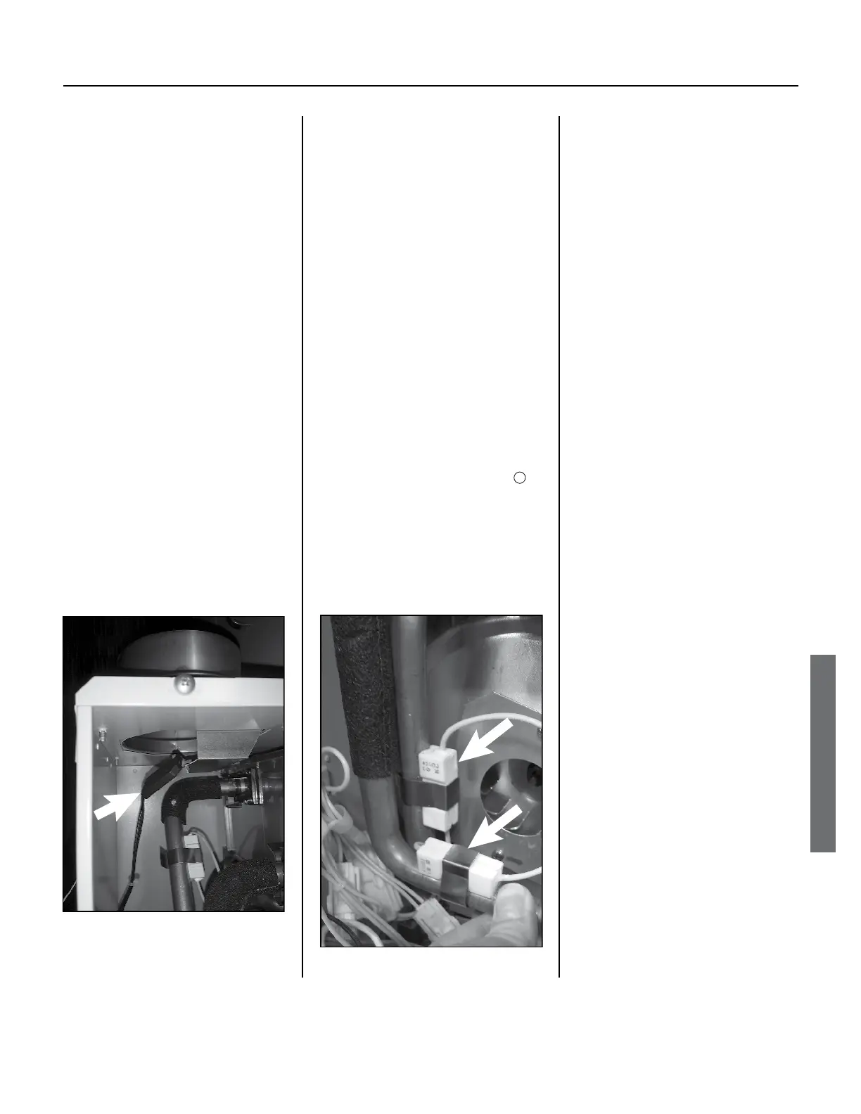
Example:
Freeze Protection Heaters
with Clips
Figure 54.
NOTICE: If you have a 540
model, you must pull a
poron of the tube out of
the bypass valve as well.
5.3
Turn the ow sensor/control
valve gently and li it o of
the inlet.
6.
(item 466, page 74) as follows:
6.1
Disconnect fastener 16-
25 (item 462, page 74)
from the top of the cold
connecon tube.
6.2
Remove two heaters and
clips (located at the top
and boom of the cold
connecon tube):
◦ Items 414 & 451, p. 74.
◦ Items 415 & 451, p. 74.
See also Figure 54.
6.3
Remove the cold connecon
tube from the heat exchanger.
6.4
Remove the cold connecon
tube from the cabinet.
7. Remove the igniter assembly:
See
following sub-steps.
7.1
Remove the screw that
secures the igniter assembly.
7.2
Disconnect the igniter
wire at the igniter rod wire
connecon.
8. Disconnect the blue wires from
the high limit switch. See “High
Limit Switch (Heat Exchanger),”
Indoor Models:
Freeze Protection Thermostat
Hangs from Air Intake Vent.
Figure 53.

 Loading...