Common to F70A/F70/F71 Series
● Notes on usage
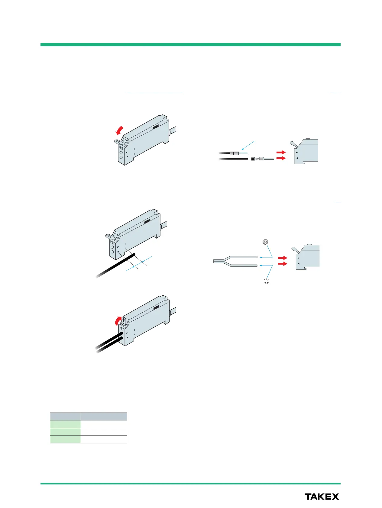
● Attachment of fiber optic cable
Attachment to amplifier
Attachment of coaxial reflective fiber optic cable
1. Open the case cover and press down the single-touch lock
lever.
●
When using two or more amplifiers joined together, be sure
to use a DIN rail for mounting.
Different ambient temperatures apply according to the
number of joined amplifiers.
●
Be sure to turn off the power supply before wiring.
●
To extend the cord, use wires of at least 0.3 mm
2
and limit
the length to within 100 m.
●
Using the same conduit for the amplifier wiring and power
transmission or high-voltage lines may cause faulty operation
or damage due to noise. Be sure to route them separately.
●
Make sure that the power fluctuation is within an allowable
range so that the power input will not exceed the rating.
●
When using a commercially-available switching regulator,
use the frame ground or ground terminal.
●
For output, avoid the transient condition (0.5 seconds)
immediately after power-up.
●
Do not use the sensor in a place subject to steam, large
amount of dust or direct exposure to water or oil.
●
Do not use the sensor outdoors or in a place subject to direct
disturbing light on the light receiving surface.
●
Use of a reflective-type fiber optic cable at the maximum
sensitivity may cause inadequate light blocking. Be sure to
use a work for sensitivity setting.
Attach the multi-core fiber to the receiver and single-core fiber
to the transmitter.
Attachment of small-diameter fiber optic cable
When attaching a small-diameter fiber optic cable, use the
adapter that comes with the fiber optic cable.
2. Insert the fiber optic cable all the
way until it stops.
To prevent inadequate insertion of a
fiber optic cable, marks to indicate
the insertion length are provided on
the case side, which can be used as
gauges.
3. Liftthesingle-touchlocklever.
No. of amplifiers
1-3
4-10
11-16
Ambient temperature
−25 - +55 ºC
−25 - +50 ºC
−25 - +45 ºC