EasyManua.ls Logo

Takex F71 Series - User Manual

Takex F71 Series
11 pages
Print Icon
To Next Page IconTo Next Page
Loading...
Operation-mode switches between
Light-ON and Dark-ON /timer
output switch
Fine-tuning available with
8-turn sensitivity adjustment
Position indicator
8/4 switch for setting Anti
Interference feature
Self-diagnosis stability indication
Flashes to indicate degradation
of received light intensity
Adjacent installation of up to 8 units
- Proprietary Anti Interference feature is used -
High-accuracy-8-turn sensitivity adjustment
- Position indicator is provided -
High-speed response of 30 μs
- H type sensor -
Variation
Manual high
performance model
High-accuracy 8-turn adjustment is equipped with a
position indicator, which allows direct reading of the
adjustment position.
F71series
Manual setting
Fiber optic sensors
Type
Manual setting
general-purpose
type
Manual setting
high-speed type
NPN output
F71R
F71G
F71B
F71W
F71RH
F71GH
F71BH
F71WH
PNP output
F71RPN
F71GPN
F71BPN
F71WPN
F71RHPN
F71GHPN
F71BHPN
F71WHPN
Light source
Red LED
Green LED
Blue LED
White LED
Red LED
Green LED
Blue LED
White LED
Output mode
Open collector
(NPN/PNP)
Model
Question and Answer IconNeed help?

Do you have a question about the Takex F71 Series and is the answer not in the manual?

Summary

Variation

Manual setting general-purpose type

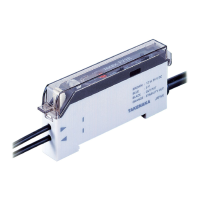
Lists models for general-purpose manual setting.

Manual setting high-speed type

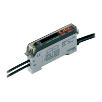
Lists models for high-speed manual setting.

Manual high performance model

Optical transmission-type Anti Interference feature

Easy-to-understand stability function

Timer operation

Turbo function increases detecting distance by 30%

Amplifier (main unit)

Fiber optic cable

Information on available fiber optic cables.

M8 connector type

Details the M8 connector type availability and identification.

Optional parts

Lists available optional parts like mounting brackets.

Environmental Specification

Input;Output Circuit and Connection

Output circuit diagram

Provides visual diagrams of output circuits for NPN and PNP types.

M8 Connector Type IO Specification;Pin Arrangement;Lead Colors

Dimensions of cord with M8 connector (optional) (in mm)

For Correct Use

Handling of amplifier case cover

Instructions for opening and closing the amplifier case cover.

Attaching amplifier on DIN rail or mounting bracket

Guidance on mounting the amplifier unit on a DIN rail or bracket.

Attachment of amplifiers for joined use

Steps for joining multiple amplifiers together for use.

For Correct Use

Attachment of fiber optic cable

Instructions for attaching fiber optic cables to the amplifier.

Attachment of small-diameter fiber optic cable

Guidance on attaching small-diameter fiber optic cables using an adapter.

Attachment of coaxial reflective fiber optic cable

Instructions for attaching coaxial reflective fiber optic cables.

Notes on usage

Important usage notes, including wiring, power, and environmental considerations.

For Correct Use

Part names

Identifies key components of the F71 series sensors.

Stability output

Explains the function and behavior of the stability output signal.

Sensitivity adjustment

Details the process for adjusting sensitivity using the SENS volume.

Anti Mutual Interference;turbo function

Detecting distance for -H type

Grouping amplifiers for interference prevention

Dimensions (in mm)

M8 connector type

Provides dimensions for the M8 connector type amplifier.

Overview

TAKEX F71 Series Fiber Optic Sensors

The TAKEX F71 Series offers a range of high-performance fiber optic sensors designed for precise detection in various industrial applications. These sensors feature advanced capabilities, including high-accuracy sensitivity adjustment, rapid response times, and robust anti-interference mechanisms, making them suitable for demanding environments.

Function Description

The F71 Series sensors operate by detecting changes in light intensity through fiber optic cables. They are available in both general-purpose and high-speed types, with NPN and PNP output options. The sensors utilize different light sources—Red, Green, Blue, and White LEDs—to accommodate diverse detection requirements.

A key feature is the high-accuracy 8-turn sensitivity adjustment, which allows for fine-tuning of the detection threshold. A position indicator is integrated to provide direct visual feedback of the adjustment position, simplifying setup and ensuring consistent performance.

For applications requiring multiple sensors in close proximity, the F71 Series incorporates a proprietary Anti-Interference feature. This prevents false operations caused by mutual interference between adjacent units, supporting installations of up to 8 sensors. The anti-interference function can be configured for 4 or 8 units, with corresponding response times.

The sensors also include a stability function that monitors the received light level. If the received light level drops to 120% or lower of the activation level for four consecutive detections, a stability output is activated, and the stability indicator flashes an alert. This feature helps in early detection of degradation in received light intensity, facilitating proactive maintenance.

A Turbo function is available to increase the detecting distance by approximately 30% when enabled. This is particularly useful in situations where extended detection ranges are required under existing conditions.

Timer operation provides a delay timer of about 40 ms, offering flexibility for various input conditions and helping to stabilize detection output by canceling signal chattering.

Important Technical Specifications

Power Supply: 12-24V DC ±10% with a ripple of 10% max. Current Consumption:

  • NPN type: 35 mA max.
  • PNP type: 40 mA max.

Output: Open collector output (NPN: sink current 100 mA, PNP: source current 100 mA). Residual voltage is 1V or less. Response Time:

  • With Anti-Interference switch at 4 (turbo function disabled): 250 µs max.
  • With Anti-Interference switch at 8 (turbo function enabled): 500 µs max.
  • High-speed (H type) models: 30 µs max. (Note: Detecting distance for H-type is reduced by roughly 30% compared to ordinary types).

Light Sources (Wavelength):

  • Red LED: 660 nm
  • Green LED: 525 nm
  • Blue LED: 470 nm
  • White LED

Indicators:

  • Operation indicator: Orange LED
  • Stability (STB) indicator: Green LED

Sensitivity Adjustment: SENS volume (8-turn without stopper, with indicator).

Switches:

  • Light-ON/Dark-ON selector switch (L.ON/D.ON)
  • Timer selector switch (NOR/ON.D/OFF.D)
  • Anti Mutual Interference/Turbo mode selector switch (common for 4 or 8 units, turbo function enabled/disabled)

Short Circuit Protection: Provided Material: Polycarbonate Connection: Permanently attached cord (outer dimension: dia. 4.8, 0.2sq. 4 core 2m length). M8 connector type also available (-J type). Mass: Approx. 90g (including 2m cord and mounting bracket).

Environmental Specifications:

  • Ambient Light: Incandescent lamp: 10,000 lx max. / Sunlight: 20,000 lx max.
  • Ambient Temperature:
    • 1-3 adjacent units: -25 to +55 °C
    • 4-10 adjacent units: -25 to +50 °C
    • 11-16 adjacent units: -25 to +45 °C
    • Storage: -40 to +70 °C (non-freezing)
  • Ambient Humidity: 35-85%RH (non-condensing)
  • Protective Structure: IP40
  • Noise: Power supply line: 500 V / Cycle: 10 ms / Pulse duration: 1 µs. Radiation: 1 kV / Cycle: 10 ms / Pulse duration 1 µs (with noise simulator).
  • Vibration: 10-55 Hz / 1.5 mm amplitude / 2 hours each in 3 directions.
  • Shock: 100 m/s² / 3 times each in 3 directions.
  • Dielectric Withstanding: 1,000 VAC for 1 minute.
  • Insulation Resistance: 500 VDC, 20 MΩ max.

Usage Features

Adjacent Installation:

  • The Anti-Interference feature allows up to 8 units to be installed adjacently without mutual interference.
  • For optimal performance, units should be mounted on a DIN rail, ensuring transmission windows are aligned.
  • Light shielding stickers (accessory) can be used to group amplifiers into blocks, especially when using more than one sensor or in strong ambient light conditions.
  • It is crucial that the selector switch settings (either "4" or "8") are consistent within one block for the Anti-Interference feature to work correctly.

Sensitivity Adjustment (Reflective Type - Light-ON Mode):

  1. Place the object to be detected. Gradually turn up the SENS volume from Min until the operation indicator (orange LED) illuminates (Point A).
  2. Remove the object. Gradually turn down the SENS volume from Max until the operation indicator goes out (Point B).
  3. Set the volume midway between Point A and B.
  4. Verify that the stability indicator (green LED) illuminates with the object in place.

Sensitivity Adjustment (Through-beam Type - Light-ON Mode):

  1. With the object removed, turn up the SENS volume to Max. Ensure the operation indicator (orange LED) and stability indicator (green LED) are illuminated.
  2. Turn down the SENS volume from Max until the operation indicator goes out (Point A).
  3. Place the object. Gradually turn up the SENS volume until the operation indicator (orange LED) illuminates (Point B).
  4. Set the volume midway between Point A and B.
  5. Verify that the stability indicator (green LED) illuminates with the object removed.

Mounting:

  • Amplifiers can be mounted on a DIN rail. Optional end units (FA7EU) are available to secure groups of amplifiers.
  • Mounting brackets (AC-BF2) are also available for amplifier unit mounting.
  • When joining multiple amplifiers, mount one at a time on the DIN rail, keeping a space, then slide them together to connect the tabs and connector pins.

Fiber Optic Cable Attachment:

  1. Open the case cover and press down the single-touch lock lever.
  2. Insert the fiber optic cable all the way until it stops (insertion length about 13mm).
  3. Lift the single-touch lock lever to secure the cable.
  • For small-diameter fiber optic cables, use the provided adapter.
  • For coaxial reflective fiber optic cables, attach the multi-core fiber to the receiver and single-core fiber to the transmitter.

Maintenance Features

Stability Output:

  • The stability output provides a continuous check on the received light intensity level.
  • It activates and the stability indicator flashes when the received light level is between 100% and 120% of the activation level, signaling potential degradation or environmental changes. This allows for proactive intervention before detection failures occur.
  • The stability indicator illuminates steadily when the received light level is well above 120% of the activation level, confirming stable detection.

Self-Diagnosis Stability Indication:

  • The stability indicator flashes to indicate degradation of received light intensity, alerting users to potential issues that may affect performance.

General Maintenance Notes:

  • Always turn off the power supply before wiring.
  • For cord extension, use wires of at least 0.3 mm² and limit the length to within 100m.
  • Avoid routing amplifier wiring in the same conduit as power transmission or high-voltage lines to prevent noise interference.
  • Ensure power fluctuation remains within allowable limits.
  • When using switching regulators, connect to the frame ground or ground terminal.
  • Avoid transient conditions (0.5 seconds) immediately after power-up for output.
  • Do not use the sensor in environments with steam, large amounts of dust, or direct exposure to water or oil.
  • Avoid direct disturbing light on the light-receiving surface.
  • When using reflective-type fiber optic cables at maximum sensitivity, ensure proper light blocking by using a work for sensitivity setting.
  • The case cover can be opened for access to internal settings and connections. It is designed to stay at a half-opened position or can be fully removed by pulling at the hinge.

Takex F71 Series Specifications

General IconGeneral
BrandTakex
ModelF71 Series
CategoryAccessories
LanguageEnglish

Related product manuals