5
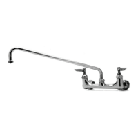
Faucet Installation:
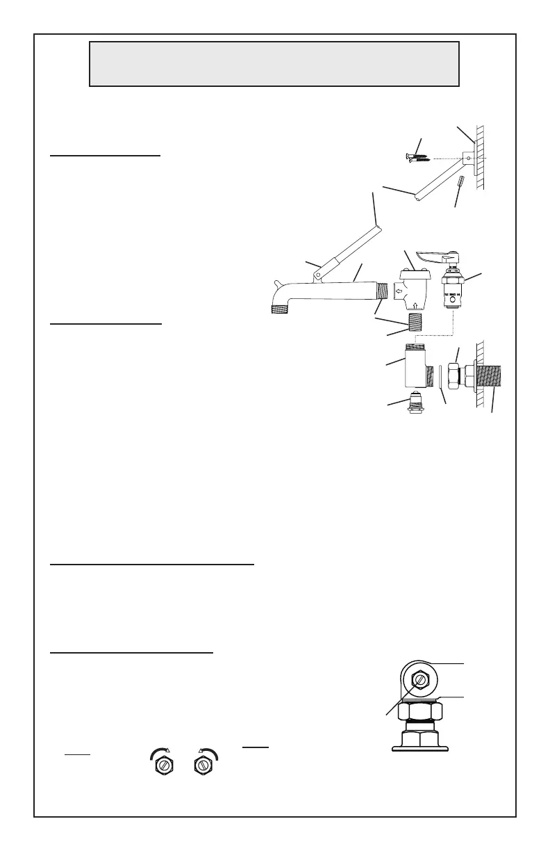
5. Shut off water supply and drain
lines. Drill (2) two 7/8” [2.2 cm] holes in wall
or backsplash of sink, 8” [20 cm] center to
center, where you are installing no.1.
6. Apply tefl on tape or pipe joint compound to
threads of water supply lines.
Note: This is a general instructional example of units using -BST.
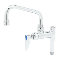
Nozzles should be installed on unit fi rst.
Nozzle Installation: ex. model B-0665-BST
1. Remove no.6 from both sides of no.1.
2. Apply Loctite #680 to threads of no.5 and no.12.
3. Insert no.12 into no.11. Thread no.5 into no.11,
then rotate no.11 into no.1 until tight with no.12
facing front of sink.
4. Replace no.6 into no.1 following
nozzle installation.
General Instructions
17
7. Remove no.2 from no.1 and attach no.2 to water supply lines fl ush against
wall. Tighten by hand. Trim supply lines if necessary.
8. Attach no.1 to no.2, adjusting center to center fi t by turning no.2 if needed.
Make sure no.3 remains in place. Tighten no.2 fi rmly with a wrench.
9. Turn on water supply and check for leaks.
Upper Nozzle Support Installation:
10. Attach no.14 to no.12 by screwing no.14 into clevis on no.12.
11. Position no.17 against wall. Mark holes and secure no.17 to wall using
no.15.
Adjusting Built-in Stops:
Insert a screwdriver to adjust no.4 at the base of
no.1 on each side. Water should be turned on
for this procedure.
no.4 adjusting
screw
Close Stop
turn clockwise
Open Stop
turn counter-
clockwise
Botton view of faucet body
and Built-in Stop
15
14
16
11
12
6
5
1
4
3
2
wall
water
supply
line
apply loctite
clevis
 Loading...