8088
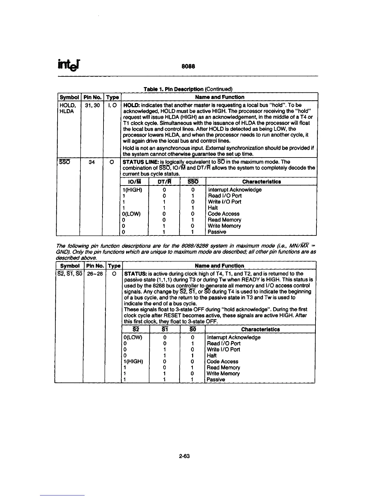
Table 1. Pin Description (Continued)
Symbol
HOLD,
HLDA
SSC5
Pin No.
31,30
34
Type
l,0
0
Name and Function
HOLD:
indicates that another master is requesting a local bus
"hold".
To be
acknowledged, HOLD must be active
HIGH.
The processor receiving the
"hold"
request will issue HLDA (HIGH) as an acknowledgement, in the middle of a T4 or
T1 clock
cycle.
Simultaneous with the issuance of HLDA the processor will float
the local bus and control lines. After HOLD is detected as being LOW, the
processor lowers HLDA, and when the processor needs to run another
cycle,
it
will again drive the local bus and control lines.
Hold is not an asynchronous input. External synchronization should be provided if
the system cannot otherwise guarantee the set up time.
STATUS
LINE:
is logical ^equivalent to SO in the maximum mode. The
combination of
SSO,
IO/M and DT/R allows the system to completely decode the
current bus cycle status.
IO/M
KHIGH)
1
1
1
0(LOW)
0
0
0
DT/R
0
0
1
1
0
0
1
1
SSO
0
1
0
1
0
1
0
1
Characteristics
Interrupt Acknowledge
Read I/O Port
Write I/O Port
Halt
Code Access
Read Memory
Write Memory
Passive
The following pin function descriptions are for the 8088/8288 system in maximum mode (i.e., MN/MX =
GND).
Only
the
pin functions
which
are unique to
maximum
mode are
described;
all other pin functions are as
described
above.
Symbol
S2.ST.S0
Pin
No.
26-28
Type
0
Name and Function
STATUS: is active during clock high of
T4,
T1,
and
T2,
and is returned to the
passive state (1,1,1) during T3 or during Tw when READY is
HIGH.
This status is
used by the 8288 bus controller to_generate all memory and I/O access control
signals. Any change by
S2,
S1,
or
SO
during T4 is used to indicate the beginning
of a bus
cycle,
and the return to the passive state in T3 and Tw is used to
indicate the end of a bus cycle.
These signals float to
3-state
OFF during "hold acknowledge". During the first
clock cycle after RESET becomes
active,
these signals are active
HIGH.
After
this first clock, they float to
3-state
OFF.
S2
0(LOW)
0
0
0
1(HIGH)
1
1
1
SI
0
0
1
1
0
0
1
1
so
0
1
0
1
0
1
0
1
Characteristics
Interrupt Acknowledge
Read I/O Port
Write I/O Port
Halt
Code Access
Read Memory
Write Memory
Passive
2-63
 Loading...