A multi-position rotary switch on the rear input panel selects either the low-impedance operating mode or the high-impedance modes
(70 V or 100 V) with available transformer taps. When using VLS Series loudspeakers in distributed line systems, the transformer
can be tapped with available power levels shown in the table below:
70 V 100 V
5 W 9.5 W
9.5 W 19 W
19 W 37.5 W
37.5 W 75 W
75 W 150 W
150 W —
All transformer primaries should be connected in parallel to the output of the amplifier. The summed total power rating in watts of the
selected tap settings for all connected loudspeakers must not exceed the total output power rating of the connected amplifier output
channel in watts. It is recommended that a generous power safety margin (minimum 3 dB headroom) be maintained between the
total loudspeaker power requirements and the amplifier output capacity to avoid continuous amplifier operation at full rated output.
Wiring the connectors
Low Impedance (8 ohms) Mode
If connecting directly to the amplifier in low impedance mode, connect the positive (+) conductor to a positive (+) barrier strip terminal
and the negative (–) conductor to a negative (–) terminal. It is preferable to connect several loudspeakers to one amplifier output in
parallel, series, or series/parallel configurations using the other internally paralleled barrier strip connector.
For more information on this, please consult the full VLS Series, Operation Manual.
Constant voltage (70 V / 100 V) Mode
In constant voltage distributed systems, normally a number of loudspeakers are connected in parallel to the single amplifier output.
Connect the positive (+) conductor from the amplifier or prior loudspeaker in the system to a positive (+) barrier strip terminal and the
negative (–) conductor to a negative (–) terminal. The other parallel barrier strip is available for connecting additional loudspeakers.
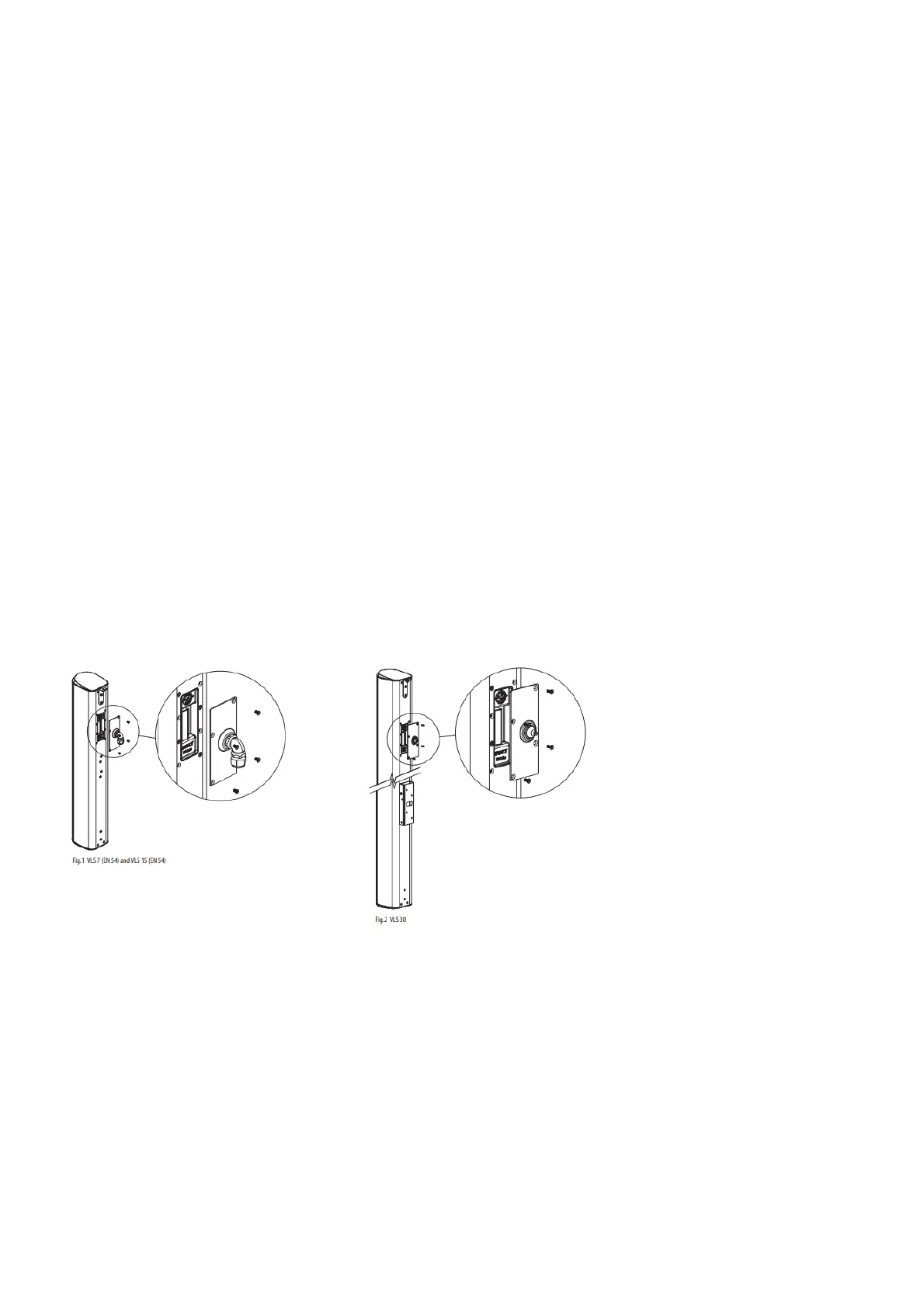
Outdoor Applications
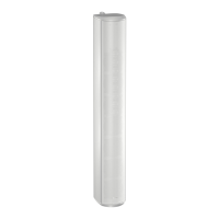
A right-angled water-tight cable gland is supplied with the VLS 7 (EN 54) and VLS 15 (EN 54) for use in outdoor applications (Fig.1).
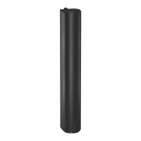
The VLS 30 has an input panel cover with a rubber wiring grommet for use in outdoor applications (Fig.2). Before making
connections, pass the wire(s) through the cable grand/rubber grommet. The input panel cover is secured to the cabinet using the four
screws already inserted around the input.
Asymmetric vertical pattern: mounting and flying
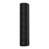
VLS Series loudspeakers are designed with an asymmetrical vertical dispersion pattern, a feature that allows improved performance
with simplified mounting in many applications. The vertical dispersion of the VLS 7 (EN 54) and VLS 15 (EN 54) models is +6/-22
degrees from the center axis, while the pattern of the VLS 30 is +3/-11 degrees from the center axis.
Please be aware of this feature when planning your installation. In many situations where conventional column loudspeakers ould
require substantial downward tilt, a VLS Series loudspeaker would require less tilt or even allow flush mounting, thus providing a
simpler installation with improved visual aesthetics.
Mounting and fixing
Wall Bracket
Each VLS Series loudspeaker is supplied with a standard wall bracket suitable for mounting on most wall surfaces. The bracket is
supplied as two interlocking U plates. One plate attaches to the rear of the loudspeaker with four supplied screws. The other part is
secured to the wall. The bar on the bottom of the speaker plate slides into the bottom notch of the wall plate, while the top is secured
with the two supplied screws. The bracket for the VLS 7 (EN 54) and VLS 15 (EN 54) is slotted to allow an angle between 0 and 6
degrees (Fig.3). Aligning the top two screw holes of the VLS 30 results in a flat flush mount; using the lower two screw positions
 Loading...