5. Wiring and connections
5.1 Connector type
EachVLSSeriesloudspeakerisequippedwithapairofinternallyparalleledbarrierstripterminalsforconnection
totheamplier(ortootherloudspeakersina70/100Vsystemorseries/parallelconguration).Barrierstrips
acceptwireupto4mmsqCSA(AWG12).Barrierstrippolarityisasindicated.
5.2 Low-impedance mode
Ifconnectingdirectlytotheamplierinlow-impedancemode,connectthepositive(+)conductortoapositive
(+)barrierstripterminalandthenegative(-)conductortoanegative(-)terminal.Severalloudspeakersmay
beconnectedtooneamplieroutputinparallel,series,orseries/parallelcongurationsusingtheother
internallyparalleledbarrierstripconnector.Pleaserefertofollowingsectiononseries/parallelconguration
before connecting.
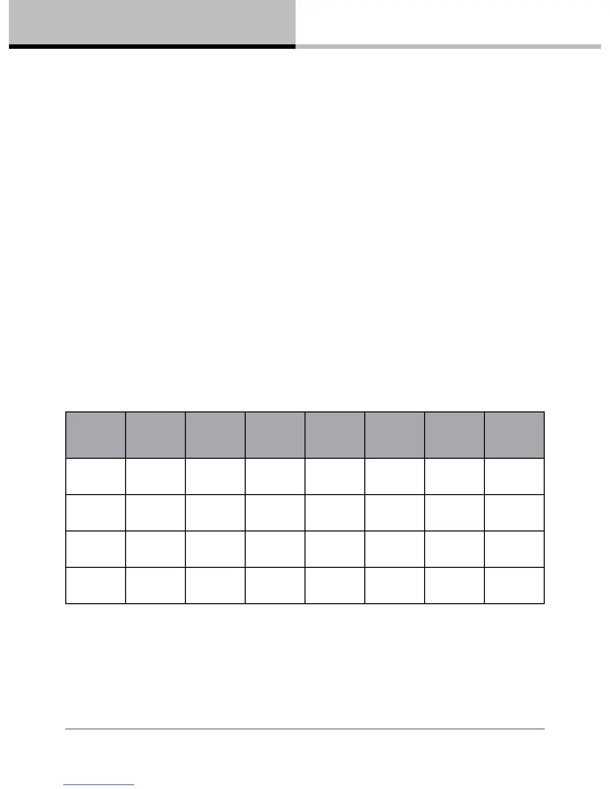
When choosing cable type, it is important to select the correct cross sectional area in relation to the cable length
and the load impedance. A small cross sectional area will increase the cable’s series resistance, inducing power
lossandresponsevariations(dampingfactor).Connectorswiredwith2.5sq.mm(12AWG)cablewillbe
satisfactory under normal conditions; with very long cable runs, the wire size should be increased. Please
refer to the following table for guidance:
Cable Run
(m)
C.S.A.of
each
conductor
(mm
2
)
AWG Cable
resistance
ohms
% Power
loss into
4 ohm load
dB loss into
4 ohm load
% Power
loss into
8 ohm load
dB loss into
4 ohm load
10 2.5
4
6
13
11
9
0.13
0.08
0.05
3.9
2.5
1.6
0.17
0.11
0.07
2.0
1.3
0.8
0.09
0.06
0.04
25 2.5
4
6
13
11
9
0.33
0.21
0.13
9.3
6.1
3.9
0.42
0.27
0.17
4.9
3.1
2.0
0.22
0.14
0.09
50 2.5
4
6
13
11
9
0.66
0.41
0.26
17.0
11.4
7.5
0.81
0.53
0.34
9.3
6.1
3.9
0.42
0.27
0.17
100 2.5
4
6
13
11
9
1.31
0.83
0.52
29.1
20.5
14.0
1.49
1.00
0.65
17.0
11.4
7.5
0.81
0.53
0.34
Amplier selection - As with all professional loudspeaker systems, the power handling is a function of voice
coilthermalcapacity.Careshouldbetakentoavoidoverdrivingtheamplierintoclipping.Damagetothe
loudspeakerwillbesustainediftheamplierisdrivenintoclippingforanyextendedperiodoftime.Headroom
ofatleast3dBshouldbeallowed.Whenevaluatinganamplier,itisimportanttotakeintoaccountits
behaviour under low impedance load conditions. A loudspeaker system is highly reactive, and with transient
signalsitcanrequiremorecurrentthanthenominalimpedancewouldindicate.Generallyahigherpower
amplierrunningfreeofdistortionwilldolessdamagetotheloudspeakerthanalowerpoweramplierthat
iscontinuallyclipping.Ahigh-poweredamplierrunningatlessthan90%ofoutputpowergenerallysounds
 Loading...