7
superiortoalowerpoweramplierrunningat100%.Anamplierwithinsufcientdrivecapabilitywillnot
allowthefullperformanceortheloudspeakertoberealised.(Seetechnicalspecicationssectionfor
recommendedamplierpower.)
Whenusingampliersfromdifferentmanufacturersinasingleinstallation,makecertainthatallampliershave
closelymatchedgains.(Variationshouldbelessthan+/-0.5dB.)Thisprecautionisimportanttotheoverall
system balance when only a single active crossover is being used with multiple cabinets. When possible, it is
recommendedthatthesameampliersbeusedthroughout.
Series/parallel connections - When running low-impedance loudspeakers in parallel, care must be
takennottoallowtheimpedancetodroptoolow,asdamagemaybesustainedbytheamplier.Mostlow
impedanceamplierswillbeabletohandleloadsof2ohmsto8ohms.Thismeansforexamplethatwhen
usinganamplierwith2ohmloadrating,uptothreeVLS30orsixVLS7/15maybeconnectedinparallel
per output, although care should be taken as impedance varies with frequency and at some frequencies the
impedance will drop to below 2 ohms.
5.3 Constant voltage (70 /100 V) Mode
In constant voltage distributed systems, normally a number of loudspeakers are connected in parallel to a single
amplieroutput.Connectthepositive(+)conductorfromtheamplierorpriorloudspeakerinthesystemtoa
positive(+)barrierstripterminalandthenegative(-)conductortoanegative(-)terminal.Theotherparallel
barrier strip is available for connecting additional loudspeakers.
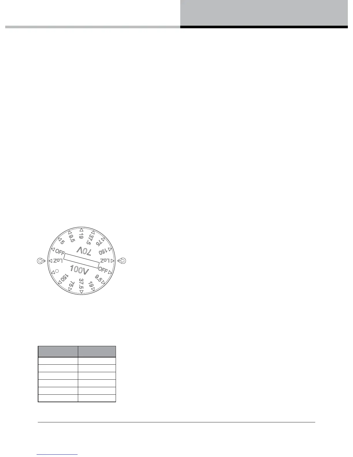
A multi-position rotary switch on the rear input panel selects either the low-impedance operating mode or the
high-impedancemodes(70Vor100V)withavailabletransformertaps.WhenusingVLSSeriesloudspeakersin
distributed line systems, the transformer can be tapped with available power levels shown in the table below:
70 V 100 V
5 W 9.5 W
9.5 W 19 W
19 W 37.5 W
37.5 W 75 W
75 W 150 W
150 W -
 Loading...