15
WARNING: Read the Operating Procedure
completely before operating your tile saw.
Take into account the working conditions from
the health and safety point of view.
Always pay extreme care and attention to the
preparation of the machine before starting.
Remove all wrenches and tools from the
machine.
Always keeps blade guard in place.
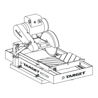
Fill the Pan (3) with enough water to fully submerge the
water pump screen. It takes approximately 6-1/2
gallons (25 l) to fill the Pan.
Before connecting the power cord:
* Check the Blade Shaft Nut (L) to be sure it is tight
and that the Blade (K) rotates freely.
WARNING: Check that the ON/OFF switch is in
the OFF position. Then connect the power cord
to a properly grounded outlet of the
correct voltage. See the decal near the power
cord for power requirements. If needed, use the
correct size three (3) conductor extension cord
to avoid excessive voltage drop. Never use lamp
cord type extensions. Refer to the
Recommended Extension Cords chart below.
Turn the switch to ON. The blade should turn
counter-clockwise, when looking at the blade guard
side. The water pump will start automatically when the
motor starts. Adjustment of the water supply may be
made by means of the Control Valve(G).
6. Lower the Blade Guard (J) and retighten the wing
nut to securely hold the guard in place.
Install the Drain Plug (P) into the front end of the pan
and fill with clean water until inlet filter of water pump is
covered; about 6.5 gal. (25 l).
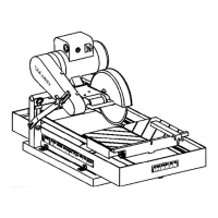
Adjust the Pan Assembly (3) to accommodate the size
of the tile to be cut and to obtain the most comfortable
position for the operator.
1. When cutting smaller tile units, adjust the pan all
the way to the rear. The operator has full view and
control of the work with minimum stretching.
2. For cutting intermediate sized units, such as 8" or
10" tile, the pan can be placed somewhere between
the maximum forward and maximum rear positions.
3. When cutting
larger units, the pan should be moved
to the maximum forward position, thus giving the
operator the best and most comfortrable position,
even when cutting 12" x 12" or larger units.
Follow the blade manufacturers recommendations for
dry or wet cutting. Wet cutting blades can be damaged
or destroyed without sufficient water. Only blades
specifically designed for dry cutting can be used with-
out coolant.
The water supply should be adequate, with
water flowing on both sides of the blade. Keep
the water clean and make certain the WATER
LEVER IS ALWAYS ABOVE THE PUMP INLET.
Do not run the water pump dry!! Unplug for dry
cutting.
For straight cuts, position the tile squarely against the
back edge of the conveyor cart. Keep the cart clean
and free of cuttings. The standard Rip Guide (R) is used.
Move the conveyor cart slowly and carefully until the
blade is in contact with the tile. The blade needs a
chance to break-in or wear-in slightly. It may take
about ten cuts to open a new blade for best cutting.
4 OPERATING PROCEDURE
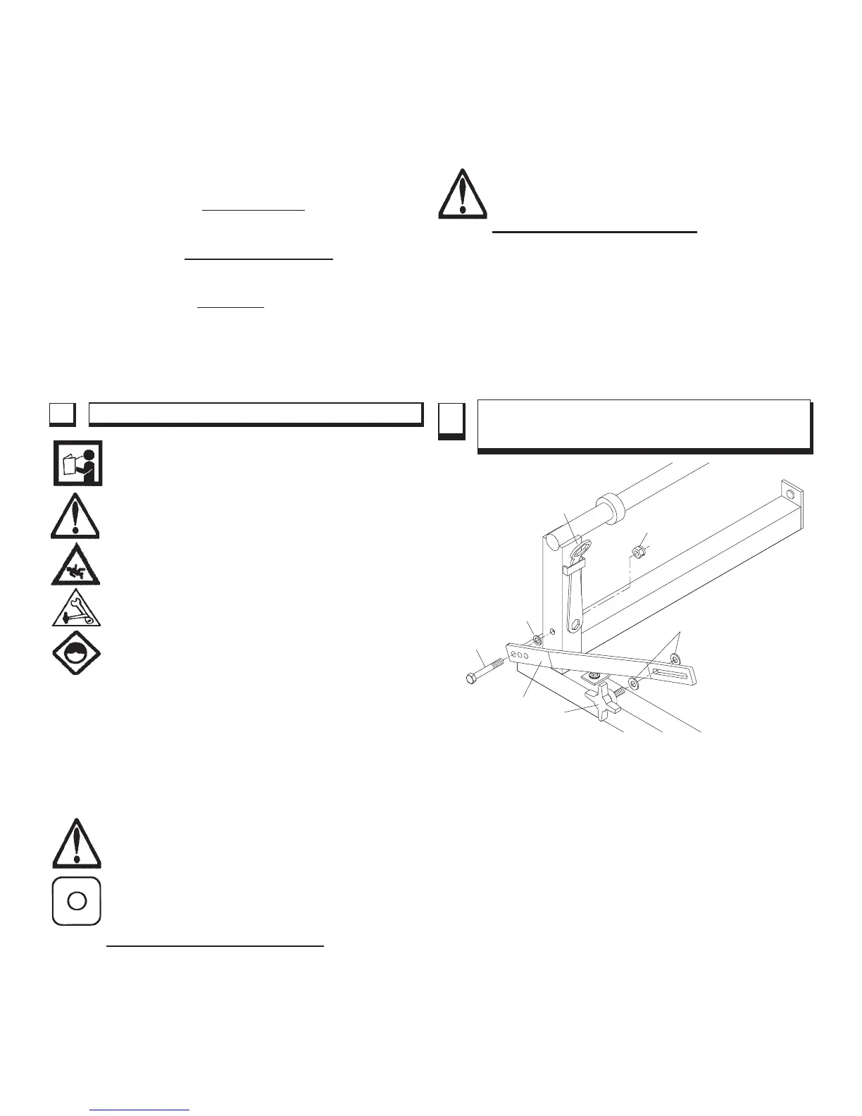
5 ADJUSTABLE LOCKBAR WITH DEPTH
LINKING PROTECTION
A Lockbar (28) is used to set the blade depth during
cutting. The lockbar has three (3) holes at the lower end
marked 10, 8 and 6.
These are used as depth-limiting settings that, if used with
the correct blade diameter, will protect the rolling cart from
being cut by the blade.
The three (3) holes in Lockbar:
10 - The lowest hole is for use with a 10" diameter
blade.
8 - The middle hole is for use with an 8" diameter
blade.
6 - The uppermost hole is for use with a 6" diameter
blade or profile wheel.
The Tilematic is shipped standard set-up for a
10" diameter blade. To change the setting, locate the
capscrew (23) used as the pivot, loosen and remove the
Lock Nut (25). Set the Lockbar ( 28) at the proper hole.
Tighten the fasteners so that the Lockbar (28) is free to
23
28
26
27
24
25
29
FIGURE 2